
We made the pads on the crystal far too large for the SMT crystals we're using. But other than that, the extra sized pads look to be just right for hand-soldering

And about half an hour later (including time taken to tin plate the entire board) here is the same board, all soldered up
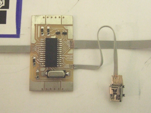
The miniature USB socket was a surface mount version, so had to be soldered onto a tiny breakout board to enable us to connect to the 0.025" pitch multi-core cable.

All that's left to do now is program the PIC and check everything works as it should. For the guitar neck, we'll need another (double-sided) PCB but for testing, we can touch the ends of the exposed multi-core wire to simulate how it will behave when wired up to the fretboard PCB.
No comments:
Post a Comment