We've not really done much on the actual instrument hardware in recent days - except perhaps finally settle on a design we're happy with. Since trying numerous ways of building the instrument from layers of acrylic, we feel we never quite got the neck/fingerboard design right. Until tonight....
This latest style - the Les Paul classic shape - now has a fingerboard slightly raised from the body join. This is how a real guitar looks- the neck may be bolted flush to the body, but the fingerboard is always slightly raised (presumably to help the player to reach those tricky 22nd and 23rd frets!)
We're going to use this design on all our guitars in future, raising the fingerboard slightly proud of the guitar body. Here's how we acheived it -
Each guitar body is made of 2 layers of 5mm acrylic (with the middles cut away to create a hollow into which the electronics are places inside the guitar body). The lower layer does not include a cut away for the guitar neck to sit in. In the old design, we would glue the 5mm guitar neck onto this lower layer, so that when the fingerboard and 3mm top body layer were placed on, they were pretty much in line.
By adding a 3mm shim on top of the bottom layer, when we put the guitar neck on, it is raised above the height of the second layer. When the final (top) layer of acrylic is in place (often a different colour to the 5mm layers) the whole assembly is flush. The fingerboard is placed on top of the neck, with the end result that it stands a few millimetres above the guitar body - just like the real thing!
Showing posts with label miniature guitar. Show all posts
Thursday, November 10, 2011
Thursday, November 3, 2011
Miniature guitars manufacturing process
Incredibly, it's November and we're still perfecting the manufacturing process for our range of miniature instruments (starting with the micro guitars). We've got the PCBs made up and have placing and soldering the components down to quite a fine art - even if we're still doing everything by hand, until we've a working pick-and-place machine.
Soldering the multi-core cable is still quite a job to do by hand but we've got it down to about five-ten minutes per instrument, including testing and resoldering should any dry joints cause problems.
One of our bottle-necks is getting the guitar strings consistently the same length and all bent to the right angle(s). These finished guitars look ok, but if you examine them closely (around the bridge and neck positions) you'll see that on some, the guitar strings look a bit bent and wiggly.
While we had the laser cutter out, we made a simple jig for bending the wires.
We went through all the guitar designs and made sure that the holes for each lined up exactly then made a template for bending our wires.
As you can see, using the jig, all our guitar strings are now neatly lined up, all the same length, and all entering the guitar body at the same angle. Such a simple job - but it makes such a difference!
Thursday, October 27, 2011
New guitar models added to the microband range
After spending a few days soldering up some of the new PCBs from www.pcbcart.com we fired up the laser cutter to make some enclosures for the new miniature guitars. We're working on a complete range of micro instruments at http://www.microband.co.uk and hope to have at least eight different guitar models.
We've already got
And we're hoping to complete the range with
Tonight we managed to design and cut out two of these new guitars:
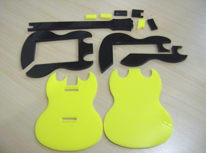
This is going to be an SG style guitar, for Andy at BandJammer.
While Angus Young from AC/DC usually plays a maroon-coloured SG, Andy's favoured guitar is a mustard yellow one (at least that's the one he uses in most of his videos and promotional material!). The closest match we could make was a yellow acrylic, but here it is partially assembled. It's a surprise gift, so let's hope he's not reading this blog!
We've some 1.5mm HIPs on order for the scratchplate. We tried making it from thick card, but it didn't look nice (and stank the workshop out with a nasty tarry smell as the laser just burned the paper and filled the cutter with smoke!). Here's the guitar we're basing this one on....
For our Les Paul style guitar, we wanted to try something a bit different to the previous styles. We've got a red Stratocaster, a yellow Explorer, a green Flying V and now another yellow guitar. A blue Les Paul just didn't look right and we don't have any gold coloured acrylic to re-create Slash's famous goldtop.
So who else plays a Les Paul and isn't Slash...?
Zakk Wylde not only plays a Les Paul, but also plays a white one, with a striking bulls-eye black-and-white pattern. Perfect! We've plenty of white acrylic in both 3mm and 5mm!
Unlike previous miniature guitars, we've moved away from the 5mm black acrylic, and decided to make the entire body from the same colour, yet stick with a black fretboard. The end result is actually quite nice.
A few stickers and a bit of finishing off and we shouldn't be too far away from the real thing -
We've already got
And we're hoping to complete the range with
- Les Paul
- Warlock
- Telecaster
- Gibson SG (AC/DC)
- F-hole blues (like BB King's Lucille)
Tonight we managed to design and cut out two of these new guitars:
This is going to be an SG style guitar, for Andy at BandJammer.
While Angus Young from AC/DC usually plays a maroon-coloured SG, Andy's favoured guitar is a mustard yellow one (at least that's the one he uses in most of his videos and promotional material!). The closest match we could make was a yellow acrylic, but here it is partially assembled. It's a surprise gift, so let's hope he's not reading this blog!
We've some 1.5mm HIPs on order for the scratchplate. We tried making it from thick card, but it didn't look nice (and stank the workshop out with a nasty tarry smell as the laser just burned the paper and filled the cutter with smoke!). Here's the guitar we're basing this one on....
For our Les Paul style guitar, we wanted to try something a bit different to the previous styles. We've got a red Stratocaster, a yellow Explorer, a green Flying V and now another yellow guitar. A blue Les Paul just didn't look right and we don't have any gold coloured acrylic to re-create Slash's famous goldtop.
So who else plays a Les Paul and isn't Slash...?
Zakk Wylde not only plays a Les Paul, but also plays a white one, with a striking bulls-eye black-and-white pattern. Perfect! We've plenty of white acrylic in both 3mm and 5mm!
Unlike previous miniature guitars, we've moved away from the 5mm black acrylic, and decided to make the entire body from the same colour, yet stick with a black fretboard. The end result is actually quite nice.
A few stickers and a bit of finishing off and we shouldn't be too far away from the real thing -
Monday, October 24, 2011
PCBs arrived from PCBCart
More exciting news about the miniature instruments as our second set of PCBs from PCBCart.com arrived this afternoon. Woo-hoo! We had 200 boards made up for just under �100 - making them less than 50p each.
Here they are, ready for inserting into our first commissioned miniature guitars. The soldermask and HASL (hot-air-solder-level) finish certainly makes soldering the boards up much easier than the homebrew boards we've been struggling with so far!
Even soldering by hand with a cone-tipped iron (rather than our preferred hot-air-soldering method) was quick and easy. Ok, the first transistor we put down went a bit wonky, but that's only because we were rushing to see how quickly we could assemble a full board!
Here's the first of our new boards ready to go into the latest (commissioned) micro guitar
Back in 1991, Metallica released their eponymous "Black Album".
It is still considered by many to be their best album to date. Everything about it was black. Including the guitars. This guitar is for a 90's Metallica fan who wants to remember James Hetfield before he shaved off his handlebar moustache and cut his hair!
Here they are, ready for inserting into our first commissioned miniature guitars. The soldermask and HASL (hot-air-solder-level) finish certainly makes soldering the boards up much easier than the homebrew boards we've been struggling with so far!
The cable on the right was soldered first. As we got familiar with the method for attaching the ribbon cable, the last cable (right) has a much better finish. These cables were hand-soldered using solder paste rather than the solder pot but only because that was what was to hand!
Even soldering by hand with a cone-tipped iron (rather than our preferred hot-air-soldering method) was quick and easy. Ok, the first transistor we put down went a bit wonky, but that's only because we were rushing to see how quickly we could assemble a full board!
Here's the first of our new boards ready to go into the latest (commissioned) micro guitar
Back in 1991, Metallica released their eponymous "Black Album".
It is still considered by many to be their best album to date. Everything about it was black. Including the guitars. This guitar is for a 90's Metallica fan who wants to remember James Hetfield before he shaved off his handlebar moustache and cut his hair!
Wednesday, October 12, 2011
PCBs ordered from PCBCart.com
After receiving such great service from PCBCart.com for our earlier guitar neck part of the project, and struggling to find a quick and easy way to attach cables to our home-etched boards, we decided to put another order in for more PCBs. Soldering multi-core cable to professionally produced boards (with only the pads exposed and solder mask covering the traces) is quite easy when using a solder pot.
Soldering quarter-pitch cable to home-etched boards with exposed traces can get a little messy with bridges and shorts and traces lifting when you try to correct them and so on. Simliarly, using home-brew reflow techniques are a little difficult with tiny components on home-etched boards because when the solder paste melts, instead of it pulling the component into line over the pads, the solder sometimes runs along the traces, dragging the component with it!
Hopefully all these problems will be solved by using properly masked, professionally produced circuit boards for our little guitars. Now we can simply populate a board and either hot-air gun or bake the board to fix everything in place. We already know that soldering cable to a professionally produced board is much easier and less likely to cause faults, so while we're waiting for these new boards to arrive, we're going to buy/build a stop watch to time how long it takes to build a miniature guitar from start to finish!
For anyone interested, here's the schematic and PCB layout for the miniature guitars.
Soldering quarter-pitch cable to home-etched boards with exposed traces can get a little messy with bridges and shorts and traces lifting when you try to correct them and so on. Simliarly, using home-brew reflow techniques are a little difficult with tiny components on home-etched boards because when the solder paste melts, instead of it pulling the component into line over the pads, the solder sometimes runs along the traces, dragging the component with it!
Hopefully all these problems will be solved by using properly masked, professionally produced circuit boards for our little guitars. Now we can simply populate a board and either hot-air gun or bake the board to fix everything in place. We already know that soldering cable to a professionally produced board is much easier and less likely to cause faults, so while we're waiting for these new boards to arrive, we're going to buy/build a stop watch to time how long it takes to build a miniature guitar from start to finish!
For anyone interested, here's the schematic and PCB layout for the miniature guitars.
Tuesday, October 11, 2011
Working guitars - Flying V and Explorer
After what seems to have been months of development (and re-development) we're finally ready to ship our first two miniature guitars. The software is still in "beta" phase, so these are going to our good friends Aaron from Oomlout and Chris at HPC Laser
Here's a video showing the basic guitar functions, and the software in it's current state (including lots of "coder art" - we're techies here are Nerd Club, not artists!)
Each instrument uses an Activex exe (sorry true geeky types, Windows only until someone can write a Linux port) but the benefit of this approach is
The software shows how multiple users can share music by recording to a different track for each instrument. This demo shows an existing drum track with a guitar track being played over the top.
[video goes here]
Here's a video showing the basic guitar functions, and the software in it's current state (including lots of "coder art" - we're techies here are Nerd Club, not artists!)
Each instrument uses an Activex exe (sorry true geeky types, Windows only until someone can write a Linux port) but the benefit of this approach is
- using a different thread to actually play sounds means more responsive play
- anyone with a bit of macro-building experience can write their own software to integrate with the instruments.
The software shows how multiple users can share music by recording to a different track for each instrument. This demo shows an existing drum track with a guitar track being played over the top.
[video goes here]
Friday, September 30, 2011
Back to business - little guitars again
It's been a disruptive couple of weeks - the move from Brighton to North Wales was ok, but finding everything in the aftermath has proved a nightmare! So what better way to find out what's here, what's missing, and what's still somewhere in the depths of our monster Transit Van than to actually get making stuff.
Not having access to the tools (nor even the internet for most of the last few weeks) means quite a bit of software development has been going on. We've been working quite a bit of late on
Setting up HackLlan - a new "hackspace" in the mountains
Creating a time-line-driven sequencer for players to create and share music over the 'web
But now we've got some of our stuff out of boxes and into the hack-cupboard, it's time to get making again.
Not having access to the tools (nor even the internet for most of the last few weeks) means quite a bit of software development has been going on. We've been working quite a bit of late on
Setting up HackLlan - a new "hackspace" in the mountains
Creating a time-line-driven sequencer for players to create and share music over the 'web
But now we've got some of our stuff out of boxes and into the hack-cupboard, it's time to get making again.
a state of chaos in the new cupboard-come-office
if you can't find it, look in one of those stacking boxes...
We're actually quite excited about how well the software development is coming along, even though it's not much more than an array of samples and a piano-roll style screen. Our current guitar prototype works quite well with the software, but we're still having a few teething problems. Whether this is the software, the hardware or the firmware, we've yet to resolve. So in true "hacker" style, we've attacked all three at once.
Here's the new pcb layout, etched and ready to solder.
Before we left Brighton we were working on using a solder pot to connect the tiny fine-pitch multi-core wires to the circuit boards. We've got everything ready to go - except the components box with all our SMT stuff isn't immediately to hand. That doesn't mean it's not here. But it could just as easily mean it's somewhere in the back of a van, under a heap of household items and bedding....
Monday, September 5, 2011
Miniature Explorer and Flying V
Following the Brighton Mini MakerFaire, and taking a few days off to help out at BuildBrighton (setting up stalls, packing away again, moving to the new hackspace and so on) it's time to concentrate on actually getting these miniature instruments finished!
Aaron from Oomlout came all the way down from Halifax to Brighton, especially for the MakerFaire but had already expressed an interest in the miniature guitars, so we demonstrated our early prototype. He wanted to buy one there and then! So we've set about making a few different guitars.
Here's a Flying V being put together in green. We've only got 1.5mm in white, so all the scratchplates and accessories have to be white for now - so we're trying to pick colours that will show up the scratchplate well (we're sick of making stuff out of red, black would be a bit boring, blue a bit dark....)
Below is an Explorer-shaped guitar (as played by U2's The Edge, and James Hetfield of Metallica - although they tend to stick to black rather than bright sunshine yellow!)
Then we had to make a whole load of pick-ups and embellishments. In this case, we're cutting them from 3mm black acrylic - the square-shaped ones at the bottom are humbuckers and the middle bits get covered in chrome sticker to make them look authentic (although for a Les Paul type guitar, the pick-ups are usually gold coloured, rather than silver, but we've only got silver!)
A few different guitar accessories - single-coil pick-ups, humbuckers, and bridge supports
The guitars being assembled - the red stratocaster is our working prototype. The others are new designs, which have taken quite a bit of trial-and-error to get right!
Aaron from Oomlout came all the way down from Halifax to Brighton, especially for the MakerFaire but had already expressed an interest in the miniature guitars, so we demonstrated our early prototype. He wanted to buy one there and then! So we've set about making a few different guitars.
Here's a Flying V being put together in green. We've only got 1.5mm in white, so all the scratchplates and accessories have to be white for now - so we're trying to pick colours that will show up the scratchplate well (we're sick of making stuff out of red, black would be a bit boring, blue a bit dark....)
Thursday, September 1, 2011
Miniature guitar - working prototype
Another exciting day at Nerd Towers as we've finally completed our first working miniature guitar prototype. Not only does the instrument work as expected (touch sensitive guitar frets, and a touch-activated strummer) but the software is coming along quite nicely too.
Although the miniature instruments are HID/USB devices using a simple 8-byte buffer interface to talk back to the PC, some people may be a little uncomfortable working at such a low level. So we're creating an easy-to-use, event-driven COM object, so anyone can create their own custom software to work with the miniature instrument range.
No worrying about bitmasking, byte buffers or retrieving data - all that has been taken care of. Simply create an instance of the COM object, and write your code to respond to events such as
Obviously, not all events are available to all instruments.
The key press/release events are specific to the synths, for example, whereas only the guitar and bass ever raise the guitarFretChanged event. Such an exciting post as this wouldn't be complete without a video demonstrating a working guitar - so here goes:
[youtube video goes here]
Although the miniature instruments are HID/USB devices using a simple 8-byte buffer interface to talk back to the PC, some people may be a little uncomfortable working at such a low level. So we're creating an easy-to-use, event-driven COM object, so anyone can create their own custom software to work with the miniature instrument range.
No worrying about bitmasking, byte buffers or retrieving data - all that has been taken care of. Simply create an instance of the COM object, and write your code to respond to events such as
- x_instrumentConnected
- x_keyPressed
- x_keyReleased
- x_guitarFretChanged
- x_guitarStrummed
Obviously, not all events are available to all instruments.
The key press/release events are specific to the synths, for example, whereas only the guitar and bass ever raise the guitarFretChanged event. Such an exciting post as this wouldn't be complete without a video demonstrating a working guitar - so here goes:
[youtube video goes here]
Wednesday, August 31, 2011
Holy moley - look at these PCBs
Well just as we'd got some piezos into our little drum kits, there was a ding-dong on the door of Nerd Towers, and a DHL parcel arrived. It was the double-sided PCBs from PCBCart! Like spoilt kids at Christmas, we immediately forgot about what we were doing and ripped apart the latest present to arrive. Impressive looking stuff...
Black solder mask, hot-air-solder-levelled (HASL) contacts and lovely white silkscreen on the front:
Here's one in place on an actual miniature guitar:
We've got some tiny quarter-pitch cable soldered onto one of the PCBs already - now we just need to mount a miniature USB socket onto a board so we can try the actual device out and make sure everything works as it should!
Black solder mask, hot-air-solder-levelled (HASL) contacts and lovely white silkscreen on the front:
Here's one in place on an actual miniature guitar:
We've got some tiny quarter-pitch cable soldered onto one of the PCBs already - now we just need to mount a miniature USB socket onto a board so we can try the actual device out and make sure everything works as it should!
Monday, August 15, 2011
PCBCart order is in
We've found making consistently good double-sided PCBs quite difficult of late, especially when we're working with tiny 0.20mm traces (normally we don't go lower than 0.5mm to ensure a good trace even if the etching goes a bit awry).
Having designed the PCBs for both guitar body and neck, we spent some time looking at different providers and suppliers. There are plenty of people on eBay offering PCB manufacture and we've already been in touch with quick-teck.co.uk.
Matt from BuildBrighton suggested PCBCart and in the time it's taken other PCB manufacturers to respond to an initial request for information, these guys have built gerber files from a simple design, debugged it, confirmed and organised all the silk-screening and solder-masking and submitted the plans for manufacture.

Their response times are amazing.
I was given the task of investigating PCBCart. I posted my order to them at about midnight and went to bed. The next morning there was an email from PCBCart asking to confirm a few things - after I emailed, I got a reply within minutes (not hours or days like other fab-houses) and in less than 30 minutes and a flurry of emails, the boards were ready for production!
I was really impressed with their service and how quickly and keen they were to get everything sorted out. After filling the online quote/order form out (they even accept PayPal) and paying a rather reasonable �140 for 200 pieces, our boards are in production and we hope to have them in about 12 days. If the quality of the manufacture matches their customer support, we should have some fantastic PCBs in less than two weeks - it's taken longer than that for some of the other manufacturers to respond to our initial query.
Hopefully that will be the last piece of the miniature guitar puzzle in place and we can start assembling them for real!
Having designed the PCBs for both guitar body and neck, we spent some time looking at different providers and suppliers. There are plenty of people on eBay offering PCB manufacture and we've already been in touch with quick-teck.co.uk.
Matt from BuildBrighton suggested PCBCart and in the time it's taken other PCB manufacturers to respond to an initial request for information, these guys have built gerber files from a simple design, debugged it, confirmed and organised all the silk-screening and solder-masking and submitted the plans for manufacture.

Their response times are amazing.
I was given the task of investigating PCBCart. I posted my order to them at about midnight and went to bed. The next morning there was an email from PCBCart asking to confirm a few things - after I emailed, I got a reply within minutes (not hours or days like other fab-houses) and in less than 30 minutes and a flurry of emails, the boards were ready for production!
I was really impressed with their service and how quickly and keen they were to get everything sorted out. After filling the online quote/order form out (they even accept PayPal) and paying a rather reasonable �140 for 200 pieces, our boards are in production and we hope to have them in about 12 days. If the quality of the manufacture matches their customer support, we should have some fantastic PCBs in less than two weeks - it's taken longer than that for some of the other manufacturers to respond to our initial query.
Hopefully that will be the last piece of the miniature guitar puzzle in place and we can start assembling them for real!
Sunday, August 7, 2011
Guitar PCB with DipTrace
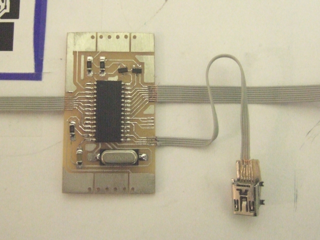
Using DIPTrace we've got an SMT version of our guitar PCB already drawn out, etched and the components laid out ready for soldering

We made the pads on the crystal far too large for the SMT crystals we're using. But other than that, the extra sized pads look to be just right for hand-soldering

And about half an hour later (including time taken to tin plate the entire board) here is the same board, all soldered up

The miniature USB socket was a surface mount version, so had to be soldered onto a tiny breakout board to enable us to connect to the 0.025" pitch multi-core cable.

All that's left to do now is program the PIC and check everything works as it should. For the guitar neck, we'll need another (double-sided) PCB but for testing, we can touch the ends of the exposed multi-core wire to simulate how it will behave when wired up to the fretboard PCB.

We made the pads on the crystal far too large for the SMT crystals we're using. But other than that, the extra sized pads look to be just right for hand-soldering

And about half an hour later (including time taken to tin plate the entire board) here is the same board, all soldered up

The miniature USB socket was a surface mount version, so had to be soldered onto a tiny breakout board to enable us to connect to the 0.025" pitch multi-core cable.

All that's left to do now is program the PIC and check everything works as it should. For the guitar neck, we'll need another (double-sided) PCB but for testing, we can touch the ends of the exposed multi-core wire to simulate how it will behave when wired up to the fretboard PCB.
Friday, August 5, 2011
Guitar PCB boards - SMT rules!
After initial reluctance, we're getting to quite like the idea of using SMT circuit boards for our miniature instruments. True, soldering them can be a bit fiddly - especially with a massive tipped soldering iron - but that can easily be fixed by using a smaller nib.
Even so, with a large tip we've managed to solder some pretty teeny little components.
Another benefit of using SMT is that everything is done on just one side of the board. With through-hole, all the components are on the "top" but on the underside are lots of little spiky bits where the component legs have been soldered to the copper board and trimmed. SMT gives us a nice flat surface on the underside to work with. A bit of double-sided tape on the unused side -

- and the board can be stuck to the acrylic "lid" of the guitar -

- and a nice flush finish, so threading the strings through from the top-side should be a doddle

Compare that to the original design, where getting the strings to line up with the holes, holding everything together AND soldering everything in place was a bit of a nightmare!

In fact, as part of our recent board edits, somehow we've managed to reduce the board length a little bit so the holes on the board don't line up with the holes on the acrylic. They're only a few millimetres out, but it will make quite a difference if we fix the board flush to the underside of the plastic. Then again, it's not a massive problem to sort that out.
There's a good chance we'll be making PCBs for a while yet, until we settle on a final design!
Even so, with a large tip we've managed to solder some pretty teeny little components.
Another benefit of using SMT is that everything is done on just one side of the board. With through-hole, all the components are on the "top" but on the underside are lots of little spiky bits where the component legs have been soldered to the copper board and trimmed. SMT gives us a nice flat surface on the underside to work with. A bit of double-sided tape on the unused side -

- and the board can be stuck to the acrylic "lid" of the guitar -

- and a nice flush finish, so threading the strings through from the top-side should be a doddle

Compare that to the original design, where getting the strings to line up with the holes, holding everything together AND soldering everything in place was a bit of a nightmare!

In fact, as part of our recent board edits, somehow we've managed to reduce the board length a little bit so the holes on the board don't line up with the holes on the acrylic. They're only a few millimetres out, but it will make quite a difference if we fix the board flush to the underside of the plastic. Then again, it's not a massive problem to sort that out.
There's a good chance we'll be making PCBs for a while yet, until we settle on a final design!
Wednesday, August 3, 2011
All-in-one guitar PCB
Since we're re-visiting old ideas (creating a neck PCB with traces rather than soldering wires to pins) we thought we'd try out another old idea - creating a single PCB for both the neck and body as one piece

It means we'll have to re-think the enclosure - at the minute it's been designed around how an actual guitar looks, with the neck raised slightly in relation to the body. If we're using a single-piece PCB, when the plastic front of the guitar is put into place, the fretboard (the reverse of the PCB) is about 3mm lower than the body. Then again, this would provide us with an opportunity to use a real wood laminate on the guitar neck for a more realistic fingerboard.
We also need to consider how the through-hole components affect the position of the guitar neck in relation to the body...

It means we'll have to re-think the enclosure - at the minute it's been designed around how an actual guitar looks, with the neck raised slightly in relation to the body. If we're using a single-piece PCB, when the plastic front of the guitar is put into place, the fretboard (the reverse of the PCB) is about 3mm lower than the body. Then again, this would provide us with an opportunity to use a real wood laminate on the guitar neck for a more realistic fingerboard.
We also need to consider how the through-hole components affect the position of the guitar neck in relation to the body...
Guitar PCB take two
Not only are we trying to make a working miniature guitar, we're also trying to find the best (and easiest) way to make a number of them, in a way which is consistent and repeatable. So far we've managed to make a working instrument, but it was really fiddly to make, and for anyone else to try to follow the same steps, it'd be pretty hit-and-miss as to how successful the end result would be (we're not mentioning that our guitar didn't actually fit into it's enclosure!)
So we're trying out an old idea again - making the neck PCB from fine (0.2mm) traces and connecting via a ribbon cable at one end. Here's the design toner transferred onto some copper clad board:

The board was cut to size to make sure it fit along the guitar neck. In fact, we can be quite loose with measurements and tolerances- at this stage, once we have a working PCB design, we can always amend the acrylic shape(s) to fit the PCB if necessary

Then the board was etched and the edges sanded and finished off nicely

Some half-pitch IDE cable was attached (I think this is 0.025" pitch cable. Whatever it is, it's about half the pitch again of "regular" hard drive IDE cable). This was acheived by tin-plating the end of the PCB first (it was too big to fit inside the glass jar we keep our tinning solution in)

Using our new tin-plating and solder-paste technique, the ribbon cable was actually quite easy to attach, even with a big fat pointed tip on the soldering iron. Maybe the fact the IDE cable was made up of single solid cores helped.
The larger "blob" of solder came off the tip of the soldering iron when we started the second piece of multicore cable. It's actually a tiny little bit of solder, but looks enormous on this photo!
The cable ends were checked for continuity and the new-style PCB put into place to make sure the ribbon cable wasn't too wide for the opening

Compare the amount of loose wire with the new board and the old one. With the new board, we could simply loop the multi-core cable under the entire main board PCB and attach to an edge connector.

We considered an alternative - creating a single, solid piece PCB for both the body and neck in one go. This has the advantage of being easier to assemble (although etching requires a shallow bath rather than our preferred "dunk-in-a-coffee-jar-of-gunk" approach) but the downside is that the guitar neck would appear lower than the guitar body (once the acrylic top layer is in place).

We were keen to keep the guitar fingerboard higher than the guitar body so that it accurately reflected the construction of a real guitar

To date the only way we can see this working is to have the guitar neck as a separate board, attached to the main board via a ribbon cable. If we used a single piece PCB, we could make the acrylic of the guitar neck from 3mm instead of 5mm to reduce the height (reducing the position of the body part of the PCB) and introduce a layer on top of the neck PCB, making it appear raised higher than the body?
So we're trying out an old idea again - making the neck PCB from fine (0.2mm) traces and connecting via a ribbon cable at one end. Here's the design toner transferred onto some copper clad board:

The board was cut to size to make sure it fit along the guitar neck. In fact, we can be quite loose with measurements and tolerances- at this stage, once we have a working PCB design, we can always amend the acrylic shape(s) to fit the PCB if necessary

Then the board was etched and the edges sanded and finished off nicely

Some half-pitch IDE cable was attached (I think this is 0.025" pitch cable. Whatever it is, it's about half the pitch again of "regular" hard drive IDE cable). This was acheived by tin-plating the end of the PCB first (it was too big to fit inside the glass jar we keep our tinning solution in)

Using our new tin-plating and solder-paste technique, the ribbon cable was actually quite easy to attach, even with a big fat pointed tip on the soldering iron. Maybe the fact the IDE cable was made up of single solid cores helped.
The larger "blob" of solder came off the tip of the soldering iron when we started the second piece of multicore cable. It's actually a tiny little bit of solder, but looks enormous on this photo!The cable ends were checked for continuity and the new-style PCB put into place to make sure the ribbon cable wasn't too wide for the opening

Compare the amount of loose wire with the new board and the old one. With the new board, we could simply loop the multi-core cable under the entire main board PCB and attach to an edge connector.

We considered an alternative - creating a single, solid piece PCB for both the body and neck in one go. This has the advantage of being easier to assemble (although etching requires a shallow bath rather than our preferred "dunk-in-a-coffee-jar-of-gunk" approach) but the downside is that the guitar neck would appear lower than the guitar body (once the acrylic top layer is in place).

We were keen to keep the guitar fingerboard higher than the guitar body so that it accurately reflected the construction of a real guitar

To date the only way we can see this working is to have the guitar neck as a separate board, attached to the main board via a ribbon cable. If we used a single piece PCB, we could make the acrylic of the guitar neck from 3mm instead of 5mm to reduce the height (reducing the position of the body part of the PCB) and introduce a layer on top of the neck PCB, making it appear raised higher than the body?
Tuesday, August 2, 2011
Almost working guitar
Using our new tin-plating and solder-paste technique, we're finding attaching IDE cables to our new PCBs a doddle! These cables were attached quickly and easily whereas usually we'd be using tons of flux, solder braid and going overtime with the solder sucker!

Here's the main "body PCB" for the guitar, populated with the PIC microcontroller, darlington transistors, crystal and discrete components to make it work

With the body circuit made up, the next job was to make the fingerboard.
The fretboard consists of 12 pairs of contacts on the top face. Each pair of contacts consists of a pin that is connected to an output on the PIC and a pin connected to the gate of a darlington transistor. When a finger is placed over the two pins (separated by about 1mm) and the output pin sent high, the transistor will switch on and pull the sensing input low (if no finger is present, the sensing input remains high because of an internal pull-up resistor).
We're connecting our finger contacts to the main board using IDE cable, so connected one pin from each of the pairs to a common sensor input pin on the PIC.

We're using 1mm PCB via pins for our contacts.
The wires will be connected to the underside (copper side) of the fretboard PCB and run inside the channel of the guitar neck

The strands of the IDE cable were separated and soldered to the pins on the "neck PCB"

With the body and neck PCBs connected together, the last bit of soldering involved putting the body PCB in the correct place on the plastic cover and threading some actual guitar strings through the face and into the rows of holes at each end of the board. With the strings in place, the ends were soldered onto the PCB and trimmed short

The last bit of assembly involved routing all the wires carefully and fixing the body and neck in place onto the actual instrument

In fact, for this prototype we learned a few things that meant we couldn't actually complete it. For example, the cavity in the middle of the guitar body needs to be measured and placed so that the PCB fits inside it - our approach was to just cut a bit out of the middle layers of 5mm black acrylic that makes up the body and just hope it would all fit together at the end!
Likewise, we learned that to get a nice finish on the strings, we need to make and use a jig for bending the wires, so that they're all exactly the same length so they don't buckle and bow as the guitar top is moved into place.
And we learned that fixing broken traces can be a real pig of a job when your PCB is stuck down inside an enclosure and you've loads of wires everywhere.
So there we have it - a sort of working guitar.
In fact, you can plug it into the USB port and use it to play samples by selecting the frets and strumming the exposed strings - the problem is, if you're not very careful, the whole lot springs open and spills its guts all over the desk!

Here's the main "body PCB" for the guitar, populated with the PIC microcontroller, darlington transistors, crystal and discrete components to make it work

With the body circuit made up, the next job was to make the fingerboard.
The fretboard consists of 12 pairs of contacts on the top face. Each pair of contacts consists of a pin that is connected to an output on the PIC and a pin connected to the gate of a darlington transistor. When a finger is placed over the two pins (separated by about 1mm) and the output pin sent high, the transistor will switch on and pull the sensing input low (if no finger is present, the sensing input remains high because of an internal pull-up resistor).
We're connecting our finger contacts to the main board using IDE cable, so connected one pin from each of the pairs to a common sensor input pin on the PIC.

We're using 1mm PCB via pins for our contacts.
The wires will be connected to the underside (copper side) of the fretboard PCB and run inside the channel of the guitar neck

The strands of the IDE cable were separated and soldered to the pins on the "neck PCB"

With the body and neck PCBs connected together, the last bit of soldering involved putting the body PCB in the correct place on the plastic cover and threading some actual guitar strings through the face and into the rows of holes at each end of the board. With the strings in place, the ends were soldered onto the PCB and trimmed short

The last bit of assembly involved routing all the wires carefully and fixing the body and neck in place onto the actual instrument

In fact, for this prototype we learned a few things that meant we couldn't actually complete it. For example, the cavity in the middle of the guitar body needs to be measured and placed so that the PCB fits inside it - our approach was to just cut a bit out of the middle layers of 5mm black acrylic that makes up the body and just hope it would all fit together at the end!
Likewise, we learned that to get a nice finish on the strings, we need to make and use a jig for bending the wires, so that they're all exactly the same length so they don't buckle and bow as the guitar top is moved into place.
And we learned that fixing broken traces can be a real pig of a job when your PCB is stuck down inside an enclosure and you've loads of wires everywhere.
So there we have it - a sort of working guitar.
In fact, you can plug it into the USB port and use it to play samples by selecting the frets and strumming the exposed strings - the problem is, if you're not very careful, the whole lot springs open and spills its guts all over the desk!
Subscribe to:
Posts (Atom)