We've been a bit busy with all kinds of projects lately, but this popped up in Google+ today and looks like a really good idea - it's a homebrew pick and place machine, based on a CNC frame.
http://hackedgadgets.com/2011/10/24/diy-pick-and-place-machine-called-the-redfrog/
But the thing that caught our imagination was the tape advance method.
The head simply drops into one of the tractor tracks on the side of the tape and pulls it along! No need for complicated electronic feeds or multiple steppers - just use the positioning head to pull the tape along to the correct place. A neat idea.
Hopefully it won't be too long before we get to try it on our own machine!
Monday, October 31, 2011
Sunday, October 30, 2011
How To Get Started Using Blender 3D
Over this past week I have been hard at work on another new project that I will post on the blog once it is farther along. In the mean time I have been asked by several people to post some help on how to get started creating 3D images and animation using Blender 3D a free software you can download online. Here is the first of a set of videos I now have posted to do just that. These videos come from a site called Blender Cookie.com. This is a perfect way to get your feet wet and start learning how to use this software. If you have not already seen some of the creations that I have made with this wonderful software check out my Blender 3D Creations page here on my blog. Also at Blender Cookie.com there are further tutorials and information that will help you to create a lot of different things once you learn the basics. I hope you will enjoy using Blender as much as I have over the past ten years.
Getting started with Blender - Interface
In this video you will learn about the Blender interface and navigation.
Getting started in Modeling with Blender - By Blender Cookie
Watch this video for an intro to modeling in Blender 3D.
Getting started with Materials in Blender - by Blender Cookie
This video will get you started with materials in Blender 3D.
Getting started with Animations in Blender - by Blender Cookie
In this video you will learn the basics of animation in Blender 3d.
Getting Started in Blender Rendering - by Blender Cookie
Here is the video to learn how to render your computer image in Blender 3D.
Getting started with Lighting in Blender - by Blender Cookie
Getting started with Lighting in Blender 3D by Blender Cookie.
Friday, October 28, 2011
Bomb Patrol in Afghanistan Uses a Robot to Blow Up an IED
You have probably seen or heard of bomb squad people before, but have you heard that they use robots to blow up the IED's. TALON is the name of the robot that the bomb squad in the video used. This robot is equipped with tank like treads, an arm with strong servos, and multiple cameras. The treads allow this bot to easily move over rough terrain. The arm sets off the bomb, and the cameras let the bomb squad men see the what kind of bomb they have found (of course, without going up close to it). TALON job to ensure that no bomb blows up and wounds or even kills a person. Thanks for reading and check out the video above to see TALON do his dangerous task!
Thursday, October 27, 2011
New guitar models added to the microband range
After spending a few days soldering up some of the new PCBs from www.pcbcart.com we fired up the laser cutter to make some enclosures for the new miniature guitars. We're working on a complete range of micro instruments at http://www.microband.co.uk and hope to have at least eight different guitar models.
We've already got
And we're hoping to complete the range with
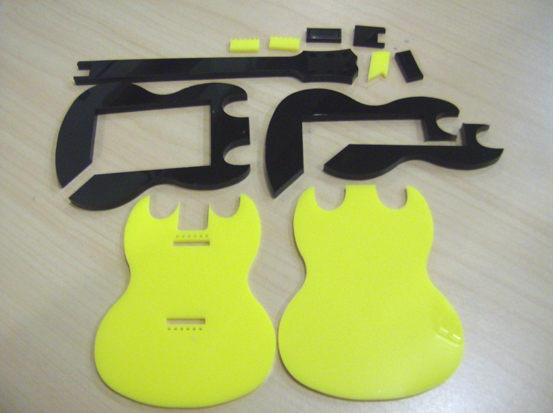
Tonight we managed to design and cut out two of these new guitars:

This is going to be an SG style guitar, for Andy at BandJammer.
While Angus Young from AC/DC usually plays a maroon-coloured SG, Andy's favoured guitar is a mustard yellow one (at least that's the one he uses in most of his videos and promotional material!). The closest match we could make was a yellow acrylic, but here it is partially assembled. It's a surprise gift, so let's hope he's not reading this blog!

We've some 1.5mm HIPs on order for the scratchplate. We tried making it from thick card, but it didn't look nice (and stank the workshop out with a nasty tarry smell as the laser just burned the paper and filled the cutter with smoke!). Here's the guitar we're basing this one on....

For our Les Paul style guitar, we wanted to try something a bit different to the previous styles. We've got a red Stratocaster, a yellow Explorer, a green Flying V and now another yellow guitar. A blue Les Paul just didn't look right and we don't have any gold coloured acrylic to re-create Slash's famous goldtop.
So who else plays a Les Paul and isn't Slash...?
Zakk Wylde not only plays a Les Paul, but also plays a white one, with a striking bulls-eye black-and-white pattern. Perfect! We've plenty of white acrylic in both 3mm and 5mm!

Unlike previous miniature guitars, we've moved away from the 5mm black acrylic, and decided to make the entire body from the same colour, yet stick with a black fretboard. The end result is actually quite nice.

A few stickers and a bit of finishing off and we shouldn't be too far away from the real thing -

We've already got
And we're hoping to complete the range with
- Les Paul
- Warlock
- Telecaster
- Gibson SG (AC/DC)
- F-hole blues (like BB King's Lucille)
Tonight we managed to design and cut out two of these new guitars:
This is going to be an SG style guitar, for Andy at BandJammer.
While Angus Young from AC/DC usually plays a maroon-coloured SG, Andy's favoured guitar is a mustard yellow one (at least that's the one he uses in most of his videos and promotional material!). The closest match we could make was a yellow acrylic, but here it is partially assembled. It's a surprise gift, so let's hope he's not reading this blog!

We've some 1.5mm HIPs on order for the scratchplate. We tried making it from thick card, but it didn't look nice (and stank the workshop out with a nasty tarry smell as the laser just burned the paper and filled the cutter with smoke!). Here's the guitar we're basing this one on....

For our Les Paul style guitar, we wanted to try something a bit different to the previous styles. We've got a red Stratocaster, a yellow Explorer, a green Flying V and now another yellow guitar. A blue Les Paul just didn't look right and we don't have any gold coloured acrylic to re-create Slash's famous goldtop.
So who else plays a Les Paul and isn't Slash...?
Zakk Wylde not only plays a Les Paul, but also plays a white one, with a striking bulls-eye black-and-white pattern. Perfect! We've plenty of white acrylic in both 3mm and 5mm!

Unlike previous miniature guitars, we've moved away from the 5mm black acrylic, and decided to make the entire body from the same colour, yet stick with a black fretboard. The end result is actually quite nice.

A few stickers and a bit of finishing off and we shouldn't be too far away from the real thing -

Wednesday, October 26, 2011
Personal review of hexbug nano
After a quick stop at Radioshack, I finally managed to get my hands on the hexbug nano. I was pretty impressed with the design, but not impressed on how innovation first ripped of the creator's design of the "bristlebot." Anyways, this bot is pretty cool, fast, small (hence the name "hexbug nano"), and maneuverable. For example, when it hits an object then it just bounces right off, and if it flips on its back then it will flip back upright. The cost of this bot was $8.99, and they come in all colors. Thanks for reading and check out my video of unboxing above!
Tuesday, October 25, 2011
NAO robot can now beg for money
Ive seen NAO do some pretty amazing things, but now NAO can beg for money! The video below was made by "TheAmazel," and he programmed his NAO to beg on the streets. Don't take my word for it; see for yourself in the video on the right. Thanks for reading and please like us on facebook or plus one us on google plus!
Info source: video above
Info source: video above
Monday, October 24, 2011
PCBs arrived from PCBCart
More exciting news about the miniature instruments as our second set of PCBs from PCBCart.com arrived this afternoon. Woo-hoo! We had 200 boards made up for just under �100 - making them less than 50p each.


Here they are, ready for inserting into our first commissioned miniature guitars. The soldermask and HASL (hot-air-solder-level) finish certainly makes soldering the boards up much easier than the homebrew boards we've been struggling with so far!


Even soldering by hand with a cone-tipped iron (rather than our preferred hot-air-soldering method) was quick and easy. Ok, the first transistor we put down went a bit wonky, but that's only because we were rushing to see how quickly we could assemble a full board!
Here's the first of our new boards ready to go into the latest (commissioned) micro guitar

Back in 1991, Metallica released their eponymous "Black Album".
It is still considered by many to be their best album to date. Everything about it was black. Including the guitars. This guitar is for a 90's Metallica fan who wants to remember James Hetfield before he shaved off his handlebar moustache and cut his hair!


Here they are, ready for inserting into our first commissioned miniature guitars. The soldermask and HASL (hot-air-solder-level) finish certainly makes soldering the boards up much easier than the homebrew boards we've been struggling with so far!


The cable on the right was soldered first. As we got familiar with the method for attaching the ribbon cable, the last cable (right) has a much better finish. These cables were hand-soldered using solder paste rather than the solder pot but only because that was what was to hand!
Even soldering by hand with a cone-tipped iron (rather than our preferred hot-air-soldering method) was quick and easy. Ok, the first transistor we put down went a bit wonky, but that's only because we were rushing to see how quickly we could assemble a full board!
Here's the first of our new boards ready to go into the latest (commissioned) micro guitar

Back in 1991, Metallica released their eponymous "Black Album".
It is still considered by many to be their best album to date. Everything about it was black. Including the guitars. This guitar is for a 90's Metallica fan who wants to remember James Hetfield before he shaved off his handlebar moustache and cut his hair!

Real Steel movie review
A few days ago I went to the movies to see "Real Steel," and its the newest movie on robots. In the beginning its starts off and at great pace, and it has scenes showing the bots right away. Later on the fights get bigger and better, but in the end the main character's bot has to fight with the strongest bot in the league. Below are some of the reasons why I like it.
- good actors
- great CGI
- action all around
- not to slow, but well paced
- has fighting robots
- good non-predictable ending
- great movie all around
- language
- violence
- dialogue (a little bit)
Sunday, October 23, 2011
Cardboard Hedgehopper Jet Build Manual Review
For some time now I have been wanting to put this video together and the information contained in it for a small toy jet that I designed and built for my son Eric many years ago. He is now finishing college so that will give you and idea how many years it has been. The jet was made using one refrigerator box! Eric loved the jet and played with it until he could no longer get into it. Anyway I finally knuckled under today and got all the information together in one place and put the plans for the jet online for sale. Here is the link to the site where you can check out more information about the Hedgehopper Jet and how to buy a set of plans.
http://store.payloadz.com/detail_html.asp?Id=973044
Here also is the sales pitch that goes along with that information and on the site you can download free sample files to check it all out.
This is a complete set of plans to build the one and only Hedgehopper Jet. A toy jet that is made from one refrigerator box Fast, easy, inexpensive construction that your children will love to play with. The plans will walk you step by step through the construction process with this 35 page manual. It has over 60 photos, 36 illustrations, and 25 technical drawings professionally prepared to make the build that much easier. The build manual also comes with 13 full size templates and another 13 full size, full color paper decals to decorate your Hedgehopper Jet once it is built. Light weight cardboard makes it safe and practically free to build when you pick it up from your local appliance store. They toss out large boxes every week and you can get them for little or nothing just for the hauling. Your son or daughter will love this big jet and it won t cost you an arm and a leg to build it. It is around five feet long with a wing span of 43 inches. It can be moved around easily and stored on it s tail when not in use. Build a squadron of them and do formations in a parade. Your kids will love owning a Hedgehopper Jet.
Saturday, October 22, 2011
Cool FANUC robot can label objects
Back then products where labeled by hand, but now its FANUC's turn! This robot is a six axis robot and its designed to quickly and smoothly, label products. It is equipped with the most accurate and agile servos and mechanics. This robot is able to complete its task with a built in IR camera, six-axis wrist, and a great overall design. Obviously this robot does a faster job than any person that labels items, and not to mention it does it better too. Thanks for reading and check out the demo video above to see this bot's labeling skills!
Friday, October 21, 2011
Makerbot Semi Sneak Preview


Jacob's Ladder CNC Case Parts
Over the past couple of days I have been cutting parts on my CNC machine. The parts will be used to make a display case for a Jacob's ladder. For those of you who do not know what this contraption is the best description I can give is this. In a lot of the old time Sci-Fi movies there is always a laboratory with a mad scientist. In this lab is a Jacob's ladder running. It is two wires that form a "V" and a large electric spark moves up this "V" getting larger and larger and it looks very scientific. My friend Steve Hamer at the QC Co-Lab maker space in Davenport Iowa built one of these devices.


This is a Blender 3D image that I put together of the Jacob's ladder case. As in real life this devise is dangerous with the use of high voltage to make it work so a display case is must. The case would be approximately two feet tall or so. Originally Steve and I thought that a plexiglass clear cylinder would be a great idea until I tried to find one online. Great idea but EXPENSIVE! So I came up with this design. The plastic for the cylinder is actually the center sections from two liter pop bottles. The labels on the bottles can be easily removed and with a little WD-40 the glue cleans off nicely.

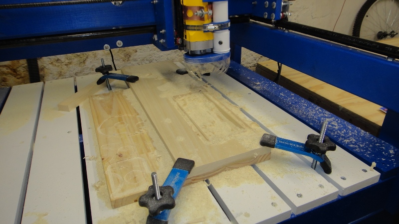
These parts make up the base and outer rings of the display case and are cut from 3/4 inch pine. I drew up the parts in my ProE design software and then did all the conversions that needed to be done in order for my CNC machine to understand what I wanted to make. This involved modeling the parts in the computer, creating a STL (stereolithography) file, sending it to Mesh Cam software which takes the STL file and creates the G-Code for the CNC machine. It sounds rather complicated but really it's just a matter of learning a bit of software and hitting the right buttons when needed. After the rings were cut out on the CNC machine I sanded them smooth with a sanding drum on my drill press. The CNC machine cutting bit leaves a rounded corner when you cut a slot so I cleaned up these up with a band saw in order to square them up for the outer support rails.

These three pieces are the outer support rails that hold the display case together. These parts were a little to large to make on my CNC machine so I marked the wood up from a drawing I created on my computer and then cut all the parts out on my band saw. It was actually faster this way and it all worked out very well. As with the wooden rings and base parts these parts were also made from 3/4 inch pine and are 23 inches long with the widest portion of the supports only being one inch wide. The notches in the parts will lock the rings and base in place when assembled. With some good wood glue it will be plenty strong enough for this display case project. I'll post more photos of the cylindrical case once Steve gets all the parts put together and painted. Hopefully I'll even get a video of the mad scientist's Jacob's ladder running. Just what we need for the QC Co-Lab.... something else scary looking and dangerous. What could be more fun to build?
Wednesday, October 19, 2011
Here's a grid of 54 blocks of colour - each with a unique combination of RGB values, one for each playing card in a regular deck (52 cards + two jokers). We're hoping to use these with a colour sensor to build a device which can "read" playing cards placed in a special holder.

Creating unique colour combinations for playing card reader
Ok. With the numerous problems and repetitions in our previous attempt, we've turned to Excel to help us solve this conundrum. We need to be sure that every playing card has a unique combination of red, green and blue in the colour block (whether we settle for a single colour in the block, or stick with the 2x2 grid approach, we'll have to wait and see, once we know how sensitive our LDR is going to be).
Each colour will have an intensity of zero-to-three.
By writing out all possible permutations, we get 64 combinations (three colours, four intensities, 4^3=64)
Each colour will have an intensity of zero-to-three.
By writing out all possible permutations, we get 64 combinations (three colours, four intensities, 4^3=64)
| Red | Green | Blue |
|---|---|---|
| 0 | 0 | 0 |
| 0 | 0 | 1 |
| 0 | 0 | 2 |
| 0 | 0 | 3 |
| 0 | 1 | 0 |
| 0 | 1 | 1 |
| 0 | 1 | 2 |
| 0 | 1 | 3 |
| 0 | 2 | 0 |
| 0 | 2 | 1 |
| 0 | 2 | 2 |
| 0 | 2 | 3 |
| 0 | 3 | 0 |
| 0 | 3 | 1 |
| 0 | 3 | 2 |
| 0 | 3 | 3 |
| 1 | 0 | 0 |
| 1 | 0 | 1 |
| 1 | 0 | 2 |
| 1 | 0 | 3 |
| 1 | 1 | 0 |
| 1 | 1 | 1 |
| 1 | 1 | 2 |
| 1 | 1 | 3 |
| 1 | 2 | 0 |
| 1 | 2 | 1 |
| 1 | 2 | 2 |
| 1 | 2 | 3 |
| 1 | 3 | 0 |
| 1 | 3 | 1 |
| 1 | 3 | 2 |
| 1 | 3 | 3 |
| 2 | 0 | 0 |
| 2 | 0 | 1 |
| 2 | 0 | 2 |
| 2 | 0 | 3 |
| 2 | 1 | 0 |
| 2 | 1 | 1 |
| 2 | 1 | 2 |
| 2 | 1 | 3 |
| 2 | 2 | 0 |
| 2 | 2 | 1 |
| 2 | 2 | 2 |
| 2 | 2 | 3 |
| 2 | 3 | 0 |
| 2 | 3 | 1 |
| 2 | 3 | 2 |
| 2 | 3 | 3 |
| 3 | 0 | 0 |
| 3 | 0 | 1 |
| 3 | 0 | 2 |
| 3 | 0 | 3 |
| 3 | 1 | 0 |
| 3 | 1 | 1 |
| 3 | 1 | 2 |
| 3 | 1 | 3 |
| 3 | 2 | 0 |
| 3 | 2 | 1 |
| 3 | 2 | 2 |
| 3 | 2 | 3 |
| 3 | 3 | 0 |
| 3 | 3 | 1 |
| 3 | 3 | 2 |
| 3 | 3 | 3 |
We only need up to 52 colours, so we've decided to do away with the "darker" colours
(e.g. a block with the colour combination 0 1 0 would have one single green square and three black ones in a 2x2 grid). The easiest way to do this was to sum the totals of RGB and any block with a total of two or less was discarded (0-1-0 gets binned, 0-1-1 gets binned, but 0-0-3 can stay, as can 0-1-2 and so on)
This leaves us with 54 colour combinations:
| Red | Green | Blue |
|---|---|---|
| 0 | 0 | 3 |
| 0 | 1 | 2 |
| 0 | 1 | 3 |
| 0 | 2 | 1 |
| 0 | 2 | 2 |
| 0 | 2 | 3 |
| 0 | 3 | 0 |
| 0 | 3 | 1 |
| 0 | 3 | 2 |
| 0 | 3 | 3 |
| 1 | 0 | 2 |
| 1 | 0 | 3 |
| 1 | 1 | 1 |
| 1 | 1 | 2 |
| 1 | 1 | 3 |
| 1 | 2 | 0 |
| 1 | 2 | 1 |
| 1 | 2 | 2 |
| 1 | 2 | 3 |
| 1 | 3 | 0 |
| 1 | 3 | 1 |
| 1 | 3 | 2 |
| 1 | 3 | 3 |
| 2 | 0 | 1 |
| 2 | 0 | 2 |
| 2 | 0 | 3 |
| 2 | 1 | 0 |
| 2 | 1 | 1 |
| 2 | 1 | 2 |
| 2 | 1 | 3 |
| 2 | 2 | 0 |
| 2 | 2 | 1 |
| 2 | 2 | 2 |
| 2 | 2 | 3 |
| 2 | 3 | 0 |
| 2 | 3 | 1 |
| 2 | 3 | 2 |
| 2 | 3 | 3 |
| 3 | 0 | 0 |
| 3 | 0 | 1 |
| 3 | 0 | 2 |
| 3 | 0 | 3 |
| 3 | 1 | 0 |
| 3 | 1 | 1 |
| 3 | 1 | 2 |
| 3 | 1 | 3 |
| 3 | 2 | 0 |
| 3 | 2 | 1 |
| 3 | 2 | 2 |
| 3 | 2 | 3 |
| 3 | 3 | 0 |
| 3 | 3 | 1 |
| 3 | 3 | 2 |
| 3 | 3 | 3 |
Where the total sum of colours in a block exceeds three (1-2-3 for example represents 1R-2G-3B) we'll have to mix the colours to make secondary colours (magenta, cyan, yellow) and maybe even black and/or white. But hopefully, using these colour intensity charts as a guide, we'll come up with colour blocks that enable us to uniquely identify a card based on the RGB values received by the LDR/light sensor.
Seeing playing cards with an LDR and RGB LED
It didn't take long after posting about our intelligent poker table for the emails to come in pointing out a few mistakes on our colour-block image.

We'd tried to come up with at least 52 unique combinations of colour blocks, using only primary (red, green, blue) and secondary (magenta, cyan, yellow) colours. We thought we'd done a pretty good job until Matt from BuildBrighton pointed out -
Looking at the top-left block of colours, it's easy to see that we've two red, one green and one blue block. Let's write this as 2R-1G-1B.
Now on the top row, look at blocks three and five.
Block three has two red, one magenta and one green.
Magenta is made up of equal parts (1:1) red and blue.
So block three is 3R-1G-1B
Block five is made up of two red, one yellow and one blue.
Yellow (as most people who paid attention in physics class will tell you) is made up of red and green light (yes, when mixing paint, yellow+blue = green, but when mixing light, red+green = yellow. Just accept it!)
This makes block five also 2R + 1R+1G + 1B = 3R-1G-1B
So although we'd used unique combinations of colour pigments for our blocks, we've actually repeated intensities of light for a lot of the colour combinations. In fact, looking through the image, we can see we've actually repeated ourselves quite a few times!
Back to the drawing board....
Intelligent poker table without RFID
As a member of HackLlan (Llangollen's Hackspace) we're trying to get some ideas together for a show-and-tell session in November and to organise a robot kit for a weekend-workshop.
This means a few of our other projects have been sidelined, while we try to find projects that are both simple enough to explain in a few hours, but complex enough to keep people's interest for the whole day.
One project we're looking at is an intelligent poker table. You know the sort - players put their cards face down on the table and a graphic appears on-screen showing their "hole" cards. This was first seen in the UK on Channel 4's Late Night Poker, where the rather lo-tech solution was to put a camera behind a sheet of glass at every player's position.

This approach is still used in a lot of televised poker tournaments, and they are available on the 'net to buy, but you'd have to be a dedicated poker player to house a full-sized 10 seater table in your house!
A variation on this theme is to have cameras mounted in the "rail" of the poker table, which sneak a peak at each player's hand, as they bend their cards upwards to have a look at them.
For home-games, an alternative approach is becoming popular, but it still quite expensive - RFID playing cards. Each card in the deck has a tiny RFID tag, and each player has an RFID reader in front of them. As the cards as placed on the reader, the unique ID is read from each tag and the system knows which cards the player holds.
This is infinitely simpler than having up to ten webcams under a table, but RFID tags are expensive. Each tag costs 50p-�1 and a professionally made deck of cards costs �100 or more. You can make your own cards, by simply applying an RFID label to each playing card, but this increases the thickness of the deck significantly and the labels are still susceptible to breaking if players bend the cards too much.
We're after a much more low-tech (i.e. cheaper solution) that should be accessible to almost anyone.
One of the ideas we're investigating is a colour sensing circuit and a 2x2 grid of colour, unique to each card.
The idea is to have an RGB LED and a light sensor (either an LDR or something like a light-to-voltage sensor) under an opening onto which the card is placed. By flashing the LED red, then measuring the amount of reflected light, then green, then blue, should allow us to work out which combination of colours is showing.
At the minute it's all just a fancy idea - but hopefully this week we'll find time to put together a proof-of-concept prototype to see if it's feasible to continue.
Tuesday, October 18, 2011
Bioloid robotic kit reviewed by generalgeek314
If you have been into building robots then most likely you know about the humanoid Bioloid robot kit. If you haven't then that's okay, because its basically just a semi-complex robotics kit that is programmable. Anyways, one of my subscribers and supporters, generalgeek314, has made a review video of this robot. In the video he goes over the tech specs about the servos, the parts, and most importantly, the micro controller. So if your thinking about buying this robot, then you this video is great for you, and its packed with seven minutes worth of tech talk! Thanks for reading and a new robot post will be coming to you tomorrow!
Monday, October 17, 2011
Cool montage of robotics
Today while browsing on YouTube I found this cool montage of robots. Even though its short, it still shows some very interesting robots like a crab robot! Just check out the video above to see it. Thanks for watching and please like us on facebook or +1 us on google +!
Interesting servo hack
After reading a few other articles about hacking servos to make them rotate continuously, I noted quite a few people suggested disconnecting the rotary pot and replacing with a voltage divider made up of 2 x 2k resistors (in a sort-of Y shape)

Our servo is much too small to fit extra components inside it, but without these, it doesn't seem to work. It spins in one direction, by sending a repeating 1ms pulse every 20ms, but increase the pulse length to 2ms and instead of running in reverse, the servo just judders and makes a nasty noise.
(if the servo is "centred" at 1.5ms, a pulse of 1ms tells it to move 90 degrees in one direction, and a pulse of 2ms tells it to move 90 degrees from centre in the other direction. By removing the pot input, the servo never knows where the head is so should continue to move).
Removing the pot seems to have caused the problem.
To simulate the pot, we soldered a piece of wire from the board where it was connected to the potentiometer (we should have snipped the end nearest the pot, not nearest the board and we could have re-used the bit of wire without extra soldering!) and connected to a voltage divider on the breadboard, made up of two 2K pots

This sort-of solved the problem, but not quite.
The servo no longer judders, but it's not not right. With a pulse width of 1ms, the servo runs at full speed in one direction. A pulse width of 2ms makes it run in the same direction, only much slower.
Maybe this is because we're using power and ground on either side of our voltage divider, rather than taking them off the internal pot (but then to get at those wires would require completely dismantling the servo!)
Now we could play about with the resistor values, or maybe even replace them with an exterior potentiometer (with the wire from the servo connected to the wiper and each end connected to power and ground) but here's a thought....
Pulling the signal on the wire to ground causes the servo to run at full speed in one direction.
Pulling it to power (5v in our case) causes the servo to run at full speed in the other direction.
So now we have a binary method of moving the servos either forwards or backwards - simply connect this new wire to an output pin and pull it high to drive the servo in one direction, and pull it low to drive it the other way.
Edit...
interestingly, we did have to make some changes to the servo control values to get the servo to work consistently without juddering. When pulling the signal pin high, we set the servo signal length to zero. When pulling the signal pin low, we set the servo signal length to 2ms. This resulted in the servo running at full speed in opposite directions. (using a signal length of 1ms and pulling low occasionally caused juddering so we ditched it!)
The downside to this approach, of course, is that we don't have a way of programmatically stopping the servos from turning. For our little robots project, we'll live with this restriction.
It's a fine balance between coming up with a project that can be completed inside a couple of hours but still demonstrates "hardware hacking" and spending all day perfecting servo controls which probably wouldn't get used!
Anyway, this is to document how we hacked our micro servos to allow us to create little tiny robots, instead of the big monstrosities normally associated with continuous rotation servos ;-)
For anyone interested, here's the Oshonsoft BASIC PIC code for our servo test board:
Define CONF_WORD = 0x3f18
Define CLOCK_FREQUENCY = 4
declarations:
Dim servolen As Word
AllDigital
init:
Config PORTB = Input
Config PORTA = Output
OPTION_REG.7 = 0 'pull-ups on PORT inputs
startup:
While PORTB.0 <> 0
'do nothing: we have to press the button to start
Wend
loop:
'button controls direction
'connect the extra wire from the servo
'to pin PORTA.1
If PORTB.0 = 0 Then
High PORTA.1
servolen = 0
Else
Low PORTA.1
servolen = 2000
Endif
'servo control signal
'for our hacked servo, signal length doesn't matter
High PORTA.0
WaitUs servolen
Low PORTA.0
WaitMs 15
Goto loop
End
Hacking to make a continuous rotation servo
As part of the up-and-coming HackLlan show-and-tell session, and for the follow-up workshop, we're making robot kits in preparation for the Robot Week Wales.
As with most robotic projects, this begins with hacking some servos to make them rotate continuously. We could just buy factory-set rotational servos from our pals at Oomlout but as the workshop is to include "hardware hacking" we figured we'd have a got at modifying some micro servos.


We snipped this lug off the cog and reassembled the servo, using the earlier photographs as reference. We then put the head back on the servo and turned it by hand, to check that it does, indeed, turn through 360 degrees. The last thing to do now is to check that the servo direction can be controlled by our microcontroller.....
As with most robotic projects, this begins with hacking some servos to make them rotate continuously. We could just buy factory-set rotational servos from our pals at Oomlout but as the workshop is to include "hardware hacking" we figured we'd have a got at modifying some micro servos.

We're after making some small, compact robots so these micro servos are the perfect size (plus of course, a ready-made continuous rotation servo is �11, a micro servo less than half this at �5 each). We already had a couple of these from an earlier project but if all goes well with this experiment, we'll be buying more!
At this stage, we're not sure if the modifications will work, but we've looked into how a servo works. It's basically a small motor with a control board. The output from the motor is geared right down, giving the servo plenty of torque (twisting power). The control board has a microcontroller and a rotary potentiometer, which is turned as the motor moves the servo "horn", which is connected to the shaft of the motor.
These easiest way to explain this is to have a look at what goes into a servo.
Whenever you take anything apart, the most important tool you can have is a digital camera - and a hammer. Hammers open anything ;-)

We put the hammer to one side and open up the servo with a tiny jeweller's screwdriver.
We actually found that the smallest flat-headed screwdriver worked better than even our smallest cross-headed 'driver (despite the servo having cross-headed screws holding it all together).
You can see that the motor shaft has plenty of cogs, gearing the output down many, many times. This is what gives the servo motor it's power.

Underneath the control board, you can just make out the rotary potentiometer. As the motor turns, the gears and cogs also turn, and the shaft on the second "pile" of cogs causes the wiper on the potentiometer to turn. This signal is fed back onto the control board, so that when the servo head has reached the required position, it knows to stop turning the motor.

We traced the wire from the pot to where it meets the control board. Taking photos (so it can be replaced later if necessary) we snipped the wire from the pot and taped it up. Now, when the motor turns, the control board won't know where the servo head is, and so will keep turning the motor.
The last thing to amend is the physical lock on the servo head.
A small "lug" on one of the cogs stops the head from turning too far during normal operation.

Sunday, October 16, 2011
Makerbot Semi Building Once Again
After months of waiting for new plastic material for our Makerbot 3D printer in Davenport Iowa, I was finally surprised and pleased to see new spools of multicolored plastic waiting for me and ready to be used at the QC Co-Lab maker space. The first thing that needed to be done was to modify the original spool setup that would only hold one color of plastic. I got an immediate brain storm once I got my hands on the new spools of material. The inner diameter of the opening was exactly two inches so I started looking for a suitable shaft that would work with this diameter. Luckily laying in the workshop of our maker space was a piece of PVC pipe. It was a diameter of one and seven eights outer diameter. It slid into the spools perfectly with enough room too spin freely. Unluckily the piece of pipe was way to short to use. I dashed off to Menards picked up a new section of pipe with some nice end caps and was set to modifying the spool holder. This is how it turned out with the help of my friend Steve Hamer at the QC Co-Lab maker space in Davenport.


The new spool holder can hold five spools of plastic for the MakerBot. For some reason we did not get a spool with the white plastic but if we had it would fit easily on to the new holder.
So with this task completed I immediately started printing parts for the Makerbot Semi I had started on weeks and weeks ago.

I had already gotten the tractor frame painted and printed (see earlier post for photos and description) so the next step was to start the cab of the semi. Now with the new colored plastic I would not have to paint the new parts.

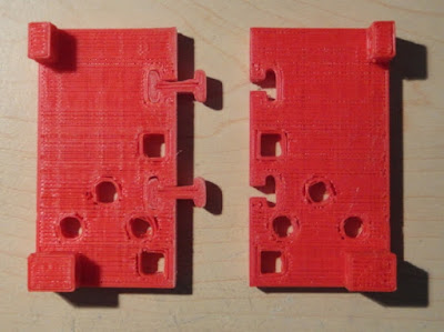
These pieces are the sides of the cab along with the floor. The floor pieces have a couple of pieces already installed in them in this photo that I call dog bones. This will hold the floor together without glue.


Here is the completed floor of the cab with the dog bones installed. The holes in the floor are the mounting holes to hold the floor in place on the frame and to mount the seats in the cab once they are printed.


These two photos are set up just like the cab floor and are of the front grill and hood assembly for the cab. I will have to make inserts for the grill in black which will make the grill stand out better once it is all put together. The parts that I printed yesterday took a total of five hours to complete. This brings the total time to print the frame and what parts you see here to 22.5 hours total. Needless to say it will be a lot more hours before the semi is completed. I will keep a running tally to let you know the grand total once it is all done. A long time to be sure. A challenge to design and build and a lot of fun along with that challenge.
Friday, October 14, 2011
Robo-Roundup #29
This weeks roundup features some very interesting robot posts, and I hope you like them!
1. The IROS 2011 Expo: http://spectrum.ieee.org/automaton/robotics/diy/iros-2011-expo-gallery
2. This robot is a pro at jenga: http://spectrum.ieee.org/automaton/robotics/industrial-robots/robot-masters-jenga-next-the-world
3. Video of IROS 2011 Expo: (to the right)
4. Coo new chinese robots can play ping-pong:
http://www.plasticpals.com/?p=30472
Thanks for reading and I hope you enjoyed it!
Thursday, October 13, 2011
A little sanding and three coats of varnish.

Wednesday, October 12, 2011
PCBs ordered from PCBCart.com
After receiving such great service from PCBCart.com for our earlier guitar neck part of the project, and struggling to find a quick and easy way to attach cables to our home-etched boards, we decided to put another order in for more PCBs. Soldering multi-core cable to professionally produced boards (with only the pads exposed and solder mask covering the traces) is quite easy when using a solder pot.
Soldering quarter-pitch cable to home-etched boards with exposed traces can get a little messy with bridges and shorts and traces lifting when you try to correct them and so on. Simliarly, using home-brew reflow techniques are a little difficult with tiny components on home-etched boards because when the solder paste melts, instead of it pulling the component into line over the pads, the solder sometimes runs along the traces, dragging the component with it!
Hopefully all these problems will be solved by using properly masked, professionally produced circuit boards for our little guitars. Now we can simply populate a board and either hot-air gun or bake the board to fix everything in place. We already know that soldering cable to a professionally produced board is much easier and less likely to cause faults, so while we're waiting for these new boards to arrive, we're going to buy/build a stop watch to time how long it takes to build a miniature guitar from start to finish!
For anyone interested, here's the schematic and PCB layout for the miniature guitars.


Tuesday, October 11, 2011
How to fix your hexbug larva if it doesn't work
If you're like me and you have a larva that won't turn on then keep reading. Ok, so first off get a tiny screw driver, your hexbug, and then unscrew the battery pack. Now take out the batteries and flip them. Thats all you have to do and you hexbug should work! Thanks for reading and watch the video above to see a video tutorial on how to fix your hexbug larva! Having any other Hexbug issues? Click here!
Working guitars - Flying V and Explorer
After what seems to have been months of development (and re-development) we're finally ready to ship our first two miniature guitars. The software is still in "beta" phase, so these are going to our good friends Aaron from Oomlout and Chris at HPC Laser
Here's a video showing the basic guitar functions, and the software in it's current state (including lots of "coder art" - we're techies here are Nerd Club, not artists!)
Each instrument uses an Activex exe (sorry true geeky types, Windows only until someone can write a Linux port) but the benefit of this approach is
The software shows how multiple users can share music by recording to a different track for each instrument. This demo shows an existing drum track with a guitar track being played over the top.
[video goes here]
Here's a video showing the basic guitar functions, and the software in it's current state (including lots of "coder art" - we're techies here are Nerd Club, not artists!)
Each instrument uses an Activex exe (sorry true geeky types, Windows only until someone can write a Linux port) but the benefit of this approach is
- using a different thread to actually play sounds means more responsive play
- anyone with a bit of macro-building experience can write their own software to integrate with the instruments.
The software shows how multiple users can share music by recording to a different track for each instrument. This demo shows an existing drum track with a guitar track being played over the top.
[video goes here]
Monday, October 10, 2011
Another Day...... Another Project
After working for a couple of days dialing in my CNC machine and reworking G-Code files I completed another small beginners project on my machine. I did about a half dozen test cuts in styrofoam so as to not waste more expensive wood and since I've got a pile of foam in my garage it was the perfect thing to use.
I wanted to make a small box for my calipers that I use on a lot of my projects. The calipers is nothing real expensive but it works and so I thought the box project would serve two purposes as I need the practice in working with CNC and the box actually could be useful. The little plastic container that my caliper came in was nothing more than a plastic blister pack. Real cheap and flimsy to be sure. I wanted something that would be a lot more sturdy.

The foam gave me a good visual as to the size of my box and if I had designed it to fit my needs. This was cut at 30 inches per minute.
 The vacuum system worked.... kind of. That was until It got clogged and I was removing very little of the sawdust that was left on my part. I cut this part at 30 inches per minute but dialed it back to 20 which worked just as well and the machine ran smoother too.

There's a part under there some place. Needless to say I removed the vacuum skirt and foot and ran a straight vacuum hose directly on the part. It was a bit messy but not anywhere near this bad. I will keep the guard when I am doing engraving or not trying to make a massive cut though wood like this one.

This looks a hundred times better. I still want to varnish the box but that is the easy part now.

Pretty close to a perfect custom fit. I'm pleased with it considering it is the most complicated piece I've tried to put together so far. A friend of mine at the Co-Lab in Davenport said that the hardest thing to make in wood is a box. After doing this little one. I believe him. Looks simple but it's not.
I'm glad to put my tools down for the day and let the dust settle.
I wanted to make a small box for my calipers that I use on a lot of my projects. The calipers is nothing real expensive but it works and so I thought the box project would serve two purposes as I need the practice in working with CNC and the box actually could be useful. The little plastic container that my caliper came in was nothing more than a plastic blister pack. Real cheap and flimsy to be sure. I wanted something that would be a lot more sturdy.

The foam gave me a good visual as to the size of my box and if I had designed it to fit my needs. This was cut at 30 inches per minute.

There's a part under there some place. Needless to say I removed the vacuum skirt and foot and ran a straight vacuum hose directly on the part. It was a bit messy but not anywhere near this bad. I will keep the guard when I am doing engraving or not trying to make a massive cut though wood like this one.

This looks a hundred times better. I still want to varnish the box but that is the easy part now.

Pretty close to a perfect custom fit. I'm pleased with it considering it is the most complicated piece I've tried to put together so far. A friend of mine at the Co-Lab in Davenport said that the hardest thing to make in wood is a box. After doing this little one. I believe him. Looks simple but it's not.
I'm glad to put my tools down for the day and let the dust settle.
Robotics in 30 years

Saturday, October 8, 2011
Robot Week Wales Wrexham
It's been a busy couple of weeks and while we've not managed to get much further on the multitude of projects we seem to be working on, we have been involved in some exciting developments.


The first thing is being involved with setting up HackLlan, a new hackspace for Llangollen and North Wales. At the minute it's a small community with a small space, but after less than a week, numbers are already increasing, and just as importantly, so is the interest in the group.
We're also looking to get involved with Robot Week Wales which is a week-long celebration of robotics, based at Techniquest in Wrexham's Glyndwr University.

And as part of the build-up to the Robot Week, we're looking to put on a show-and-tell session with other members of HackLlan, to show new potential members the kinds of things they can make at their local hackspace. This will be followed up with a more formal robot-building workshop, where attendees can make their own line-following robot.

So while all this is going on, our recent x-y plotter/cnc pick-n-place machine looks like it's going on hold. But we're determined to soldier on with our miniature instruments developement. The software is almost finished now (we've been working on it over recent weeks, while the internet connection here has been a bit intermittent) so we just need to get our guitars finished and tested and we're ready to launch a new website (details to be posted here nearer the time)
Friday, October 7, 2011
CNC.... A Real Learning Process
Over the past two days I have been working with my CNC machine trying to get to know how to make it work properly. First on the list was getting the table level with the "Z" axis so that when I want to engrave a piece that it is a constant depth throughout the entire part. I had to level the upper rails for the "X" axis so that at every corner of the table the cutting bit when touched to the part would read "Zero" on the Mach3 milling software that runs your part you want to make. I had to figure out how far out the table was in the first place and it did not look good. I started with the lower left front of the table and set my cutting bit to zero at this point. Then I checked the lower right corner. This was 3/16 of an inch lower. So was the upper two corners. In order to correct this I had to make some washer shims that I could slide under the mount for the "X" axis. This axis runs from the front to the back of the machine. The "Y" axis runs from side to side and the "Z" axis is the vertical axis the moves the cutting bit up and down. After about an hour or so of work and a couple of days of thinking about it I managed to get the table leveled to less than 1/64th of an inch on each corner. I was smiling at this point. Now I could do engravings and it would look great.
The next problem I encountered over the last two days was a problem that cropped up while trying to cut a simple little wooden box for my micrometer. I tried to cut this two part box in foam luckily as after five bad tries I was ready to pull my hair out of my head with frustration. What was happening was that the "Z" axis started to loose it's zero calibration that you set up before you start cutting a part. This calibration tells the machine that all measurements come off of the top surface of the part. The problem that cropped up was that the zero calibration started to change during the cutting of the part. In other words instead of cutting a 1/4 inch cut into the part the machine now would cut almost 1/2 inch deep cut. This made for bad parts every time. Luckily the parts were test cut in styrofoam instead of wood. Would have been a very expensive couple of days. After doing some research online I finally think I have the problem solved. I had made adjustments to the speed at which the machine cuts on all axis. I wanted the fastest possible speed without bogging the stepper motors down. Good idea but not for the "Z" axis. This axis as I said earlier moves the bit up and down into your part. But with too much speed the machine looses calibration and the cutting depth starts getting deeper and deeper somewhere in your part. I slowed the axis speed down and now it looks to be cutting correctly. One of the test pieces that had failed earlier today came out beautifully this afternoon. My sanity has been restored! Stay tuned for the final word and photos of the next finished part from the CNC machine and my workshop.
The next problem I encountered over the last two days was a problem that cropped up while trying to cut a simple little wooden box for my micrometer. I tried to cut this two part box in foam luckily as after five bad tries I was ready to pull my hair out of my head with frustration. What was happening was that the "Z" axis started to loose it's zero calibration that you set up before you start cutting a part. This calibration tells the machine that all measurements come off of the top surface of the part. The problem that cropped up was that the zero calibration started to change during the cutting of the part. In other words instead of cutting a 1/4 inch cut into the part the machine now would cut almost 1/2 inch deep cut. This made for bad parts every time. Luckily the parts were test cut in styrofoam instead of wood. Would have been a very expensive couple of days. After doing some research online I finally think I have the problem solved. I had made adjustments to the speed at which the machine cuts on all axis. I wanted the fastest possible speed without bogging the stepper motors down. Good idea but not for the "Z" axis. This axis as I said earlier moves the bit up and down into your part. But with too much speed the machine looses calibration and the cutting depth starts getting deeper and deeper somewhere in your part. I slowed the axis speed down and now it looks to be cutting correctly. One of the test pieces that had failed earlier today came out beautifully this afternoon. My sanity has been restored! Stay tuned for the final word and photos of the next finished part from the CNC machine and my workshop.
Thursday, October 6, 2011
What is BEAM Robotics
Maybe some of you have already heard about BEAM Robotics. For those who don't know exactly what a BEAM robot is I'll explain it to you in this post.
BEAM stands for:B-iologyE-lectronicsA-estheticsM-echanics
Common robots use a programmable microcontroller, which means some kind of computer, to make decisions. The more complex the behaviour of the robot the more complex the program in the microcontroller. Anyone who has already had some experience programming a robot can acknowledge this. With every new task the robot has to perform the complexity of the robot rises exponentially. It gets harder and harder to find and fix errors and to make the robot respond properly to its environment. Most developers would simply put much more effort into the "brain" of a robot to accomplish their goal. But the principle of BEAM offers another solution: Make the robot simpler by removing the microcontroller and use minimalist electronics instead. The results are much cheaper robots that can perform the same task even more efficiently than the microcontroller based ones. Another advantage of BEAM robots are that anyone can build one without even spending (much) money. The parts are easily available by reusing old components out of technoscrap. If you want to build a robot with a very simple behaviour "the common way" you'd probably spend about 50$ to 100$. If build a BEAM bot you might simply be able to do it for free. So if you want to know more about BEAM Robotics the following sites offer excellent information:"http://www.solarbotics.net/"Solarbotics"http://www.beam-wiki.org/">BEAM Wiki. Special thanks to BEAM Robotik for writing the post and his website is http://beam-robotik.blogspot.com/ !
Subscribe to:
Comments (Atom)