Here is the seventh installment of the motorcycle cargo trailer build. In this section I will cover the build of the lid for the trailer, spare tire mount, shaping of the body and the mountings of the side marker lights. So lots of info in this section to see.
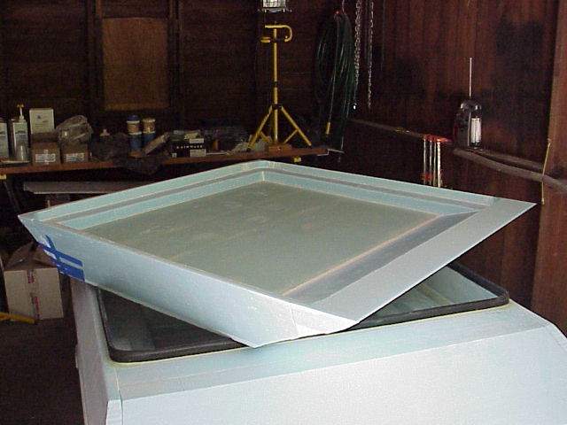
Here the outer side foam panels are taped into place on the lid of the trailer. As you can see lots of tape was used to hold the panels tight until the foam glue has dried.
To shim the lid so that the spacing is uniform around the outer perimeter of the lid I used popsicle sticks. Lots of them to get the spacing just right. Inexpensive and easy to get the spacing of the lid just right.
The trailer of course needs a spare tire and mount. This is done by taking the tire and making some simple mounts that will hold the tire in the trailer without it bouncing around when traveling down the road. The brown squares in the top of the blue foam are wooden block glassed to the foam with steel eyelets also bonded in. Bungee cords strap the tire down and are easy enough to remove if the spare is need to fix a flat tire.
Here is a couple photos of the spare tire mount glassed into the trailer and with the tire in place. It took me a while to figure out the best place to put the spare tire and yet not take up valuable cargo space. The center front mount worked great as the spare is something that you may need but rarely will use. Looked good to in this placement in the trailer.
Here the body of the trailer is on the fully assembled chassis of the trailer for the first time and finally sees the light of day. Already it looks pretty good but is way to squarish for my taste. A lot of builders at this point would just round the top edges off and glass it and call it done. Not what I wanted at all. So on to the next step that will fix all of that and make it even more professional looking once we are finished.
The next big step in the build will be setting up the templates that will help shape the trailer using the large hot wire bow. I used two panels of half inch plywood laid out on my dining room floor. I taped two pieces of scrap 1 x 2 wood together to make a giant compass to mark the arc that will make up the shape of the body of the trailer. One end was screwed loosely to one panel and the other end had a pencil taped to it. I then drew a large arc on the panel and repeated the process on the second panel in the same way.
The two panels were then cut out using a jig saw and the edges were sanded smooth using a small power sander. The panels were then mounted onto horizontal and vertical 2 x 4's so that the panels could be held in place when I needed to use the hot wire bow to cut trailer body.
Inside of the garage the wooden templates are checked for alignment for cutting the foam body of the trailer. The body is placed between the templates and rests on the lower 2 x 4's which is bolted to them to hold it all in place. You don't want the body to move when you are cutting the foam with the hot wire bow.
The body is removed from the chassis and the entire table and hot wire template assembly is brought outside for the nerve racking task of cutting the body into shape.
Here the cutting begins and my nerves are on edge during the entire process. What you cannot see in the photos are what my friend Garry (guy with the beard) and I (wearing a black shirt) are seeing. On the templates on the top edge are marks one inch apart numbered from one to 200 or so. Garry reads off the numbers as he slowly moved his side of the wire and I would move my side at the same rate matching his call out of these numbers so that the hot wire would cut evenly through the foam.
This is a good shot of the hot wire cutting through the foam and resting on the wooden template on Garry's side of the assembly. The hot wire bow is around five feet long so the wire had to be tight and be moved very very slowly so that it did not flex to much while cutting.
Here the body of the trailer has been completed cut into shape. At this point I could now breath a big sigh of relief and look forward to the next part of the project.
Back in my dining room once again I assembled this strange looking template which will be used to guide the cut of the front corners of the trailer body again with a hot wire bow.
Now you can really see why the extra effort of cutting the body paid off. The body now looks much smoother with a shape that looks like a car body instead of a cardboard box. Smiles were seen and cheers were heard throughout the workshop!
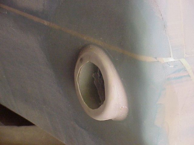
Now that the body had been shaped completely on the outside the side marker light housings could be mounted into the body. This was a simple task of just inserting the housing into the opening and bonding it into place using resin putty. Then the outer perimeter was glassed inside and out to seal the housing into place. In the last photo you can see the perimeter clearly around the rear housing of the side marker.
Lots of progress with this section of the build with all that had been done. Starting to look more and more complete at this point and the end is looking near.


No comments:
Post a Comment