Friday, June 29, 2012

CNC drilling machine update

Just a quick update after the postie dropped two rather heavy envelopes onto the doorstep of Nerd Towers this morning. The first parcel contained three 5v miniature stepper motors. These are really nice, and came from China in about 5 days. At �1.99 each with no extra p&p these could just be the bargain of the month!


The motors have lots of torque and because of the off-centre shaft, we suspect that they are really a much smaller motor inside the casing, with a number of gears to provide the torque. It's a cheap and easy way to increase the number of steps per full revolution, while keeping the power consumption/voltage/current requirements down so they can be driven through a ULN2003A darlington array (the kind we blew when driving stepper motors directly from a PIC last time!)

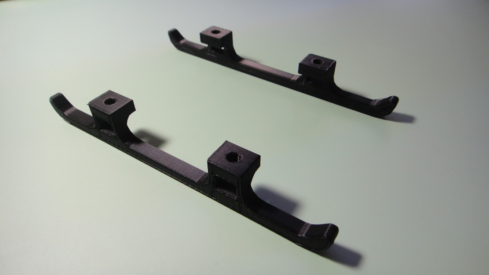
Also shown in the photo above are some drawer rails from eBay.
These are replacement parts for the kind of mechanisms commonly found in IKEA and MFI type flat-packed furniture. We got the 175mm lengths. About half of the runners run really smoothly and require little effort to push from one extreme to the other. About half have a little "sticky point" somewhere along their length. It's not an insurmountable problem, and our geared steppers should be more than enough to drive a platform mounted on these, but we're going to pick the four best/most freely running to use on our CNC drilling machine.
At �8 for ten off eBay, we've so far blown �14 of our �50 budget (we're going for the new build design to begin with, then see which parts we can swap out for salvage in a later version). Some laser cut acrylic, hot glue and bolts should see us with a working gantry in no time....

MIDI saxophone update

After another BuildBrighton meeting last night, a bit more work has been done on MIDI-fying our saxophone. This is now the third attempt and looks the most likely to get a working result! The first time, the wires were ran from the bell to the neck, leaving little or no room for the microcontrotroller circuit. The second time, the wires were run to the bell, so there was a large area we could fill with a circuit board, but the copper-tape-making-contact-with-the-body idea failed on number of pads.

This time, we're sure we've got it right. Only because, we couldn't have come up with a more difficult-to-implement solution! We're (slowly) removing each pad - yes, complete with linkages and springs - and fitting a pushbutton under each one.


In doing this, we're finding out quite a bit about the saxophone.
Namely that it's been badly dropped at some point during it's life, and would be unplayable as an acoustic instrument! There are four or five pads misaligned - and rings on the leather showing where the pad used to sit, and a shallower indent showing it's new resting position after the (presumed) accident.

So despite filling the body with hot glue and generally making a mess of things, at least we can be satisfied in knowing we're not ruining a perfectly good sax for this project - it was only destined for a junk shop somewhere, or an expensive repair job!

 (Saxophone fitted with five pushbuttons, mounted into acrylic disks. The push buttons are the slightly clicky tactile ones and the guard has been removed to allow the pads to open more fully). 

When operating the pads, it's interesting to feel the tactile clicky button through the button on the body of the sax. This gives a really nice, responsive feel.
However, some pads are "normally closed" and open when you press a key (or combination of keys) rather than the simpler push-to-close type. We found that sometimes, if you release a key gently, the spring on the pad isn't always strong enough to force the pad fully closed again. Here's an example of one such pad. An extra spring was added between the pad cover and the guard, to help push the pad into it's normally-closed state, and force the pushbutton to "click closed")


Wednesday, June 27, 2012

Today was a Sad Day :(

Yes a sad and awful day indeed... In a couple of month lot of set backs happens in my life... In this month some of my sweet dreams turned into scary nightmares...some of my hopes and wishes washed away... and today was another sad day...


 Alas, my laptop hard disk crashed without any signature... It showed no indication of failure.... All the family photos, my 1 year of research and lot of programming applications, my circuits and all good stuff went into holy grave :(..

Yes.. Today is very sad day ...

Robot plays "rock paper scissors" and wins 100% of the time

Usually we just play rock paper scissors with each other, but now theres a robot that can play too! Developed at the University of Tokyo, this robot is able to win every game 100% of the time. It's high speed cameras allow this to happen by tracking the opponents hand movements. After it detects the movement and formation of the hand, it quickly makes a move to beat the opponent. All this happens in a split second too. You can check out the below above to see it in action. Thanks for reading and check back tomorrow for a new post!


Tuesday, June 26, 2012

ABB robot plays snooker


The precision of these robots are just absolutely stunning. Especially when they can move the tips of there arms in and out of a line of pool balls. This just comes to show that these robots really are advanced.

CNC drilling challenge

As part of the recent BuildBrighton MIDI workshop, we had to produce about twenty homebrew PCBs. The print and etching part was easy, but what took ages was drilling all the holes for the through-hole components.

There's no doubt that surface mount makes things easy, but when sharing designs and ideas, plenty of people are still firmly in the through-hole camp. So we try to reflect this when making boards for other people to use. Despite having a cnc machine at the 'space, and having access to a second one, the prospect of learning MACH3 and getting all the settings right to drill the holes with the cnc just left us cold. Also, getting everything out, set up, drill the boards, then dismantled and put back away again was going to be a big job (these cnc machines are big beasts and take up a lot of room, so we put them away when not in use!)
We felt it would be quicker for a few of us to just fit a tiny bit into a dremel and go for it by hand.
So this is what we did.

But drilling by hand was a real PITA too, so after this weekend, a few of the BuildBrighton members have set a challenge: To make as small and as cheap a cnc drilling machine as possible.

That description was a bit vague, so we've come up with some "rules":

  • If buying all new components, not more than �50 on the entire build (just think about it, a cnc based device for under �50!)
  • If using salvaged hardware (stepper motors from old printers, for example) not more than �20 total build cost
  • As we're building a small machine, the footprint of the device, when put away, should not exceed A4 size (210x297mm)
  • But it'd be useless if it could only drill tiny pcbs, so it has to be able to drill up to half eurocard sized boards (100x80mm)
  • Any bought components should be accessible to everyone and you should reasonably expect to be able to purchase the same components from the same, or alternative suppliers 12 months from now (so you can't win a job lot of motors from some bloke off ebay and put cost of materials down as 50p)
  • Overseas suppliers can be used to keep costs down, as their price per unit is often much less than UK suppliers.
  • The device is to be platform independent - it can use any microcontroller and any software can be used to control the machine, including homemade software/drivers. 
  • It has only to work on any one platform, not all
  • For accuracy, the drilling machine should be able to drill a 1mm hole in a max-sized 2mm pad and leave a complete copper ring intact around the hole
  • For building materials, assume a price for acrylic sheets as �1 per mm thickness, per A4 sheet
  • Cheaper alternatives (such as mdf or laser ply) can be used instead of acrylic for the chassis if required
  • Trivial components and the cost of pcb etching, running a laser cutter etc and consumables will not be used to calculate total build cost
  • The price for delivery of all components bought online will be included in the final cost

More rules may be added as the build goes on, but only to clarify any points that may arise, not to act as a restrictive force to deter alternative ideas.

So there we have it. Another stupid challenge that probably won't get finished (or much beyond the planning stages) But it always nice to have an excuse to sit around with a brew and kick about a few ideas with like-minded people.

For our build, we're going for cheap AND small.
Most other people have concentrated on one or the other. We're more than willing to sacrifice accuracy for cost, or cost for size, or size for comedy value. As always, sporadic updates, in-between other projects, will get posted here as the build develops.....

Another Good Day On The Gyrokite Project


The Gyrokite project continues today with these photos of the parts that I made on my Makerbot 3D printer of the landing skid assembly.  


This is one of the landing skids for the Gyrokite.  Both skids are exactly the same and I designed them to be symmetrical in shape so that I did not need to have a left and right skid for the project.  The skid is 1/4 inch square at the base and is 6 inches long by 7/8ths of an inch tall.


This is the skids by themselves as they would be set up for the assembly of the landing skids.


Here the cross members are added to the assembly with 10-32 bolts and nuts.  The nuts are inserted into receiving slots in the landing skids and the bolts then are inserted through mounting holes in the cross members to hold it all together.  


These last two photos show the addition of the internal mast framework for the rotor blades mounting shaft.  This part has internal slots again to mount the part to the rear cross member with more 10-32 hardware.  On the sides of the mast framework are additional mounting holes with fuselage.  Internal nuts are recessed into matching holes to hold the nuts in place when attaching the fuselage side to the internal framework.  This will make more sense once the final assembly has taken place and I can get photos of it all going together posted here. 
All of the parts for the landing skid assembly that I have shown you here are not filled solid with plastic from the Makerbot printer.  In actuality the parts are internally crisscrossed with a honeycomb of plastic to give each part strength yet make them lightweight. This will help a lot in keeping the weight down on the entire assembly when I want to fly it.  

  On another note about this project as it was quite windy here yesterday I did a little test of one of the main rotors from a suggestion made by my brother Dennis.  I took the rotor shaft and one of the rotor blades and just held them at arms length into the wind to see how well it would spin.  To put it simply....WOW!  I was just barely able to hold it away from my body as the blade being three feet long was whipping around on the shaft at quite a speed.  Even enough speed to make an actual helicopter sound as it spun up in revolutions. WHOOP, WHOOP, WHOOP!  I am more encouraged now that this project has a real chance of working out the way I have planned.  If all else fails that I do not get enough lift from the 36 inch rotors I can always make them longer and try again.  But for now I think these will work out just fine.  A good test to be sure and another good day at the Tinker's Workshop!

Monday, June 25, 2012

Robotic arm controlled via flex sensor

In this video I found on youtube, it shows a robot hobbyist controlling his robotic arm with a flex sensor. The sensor is attached to a glove, and when he bends his fingers (the fingers are in the glove obviously) the robot arm then moves. Thinks thats interesting, then check out the video above!

The Gyrokite Project Continues


In my last post I started work on an update of an old design of a gyrocopter kite that was made in the 1960's.  Today I will show you another couple of steps in the process of building the Gyrokite.  These being the tail section and the main rotors. 
  The tail section of the gyro is made out of fiberglass which looks complicated to make but when broken down to simple steps is very easy to build.


I started first with an inch and half block of blue styrofoam nine inches wide and six inches long.  This is the exact same stuff that you put into your house to insulate it from the cold and can be bought at your local home supply store...aka Lowes, Menards, etc.  The block is cut on both sides at a 45 degree angle and then the top edges are rounded off using sandpaper. 


Next four layers of 8 oz. fiberglass cloth and resin are applied to the surface of the block making sure that at least four inches of the block are covered with uniform smooth layers.  This will make the actual surface of the tail section.


After the fiberglass has cured over night the block is cut using a band saw.  The three inch wide middle section is what I was after and the rest of the material can be scrapped.


I then did some additional marking on the newly cut block to get the outline of the tail section that will be cut next again using the band saw.


Here the tail section is starting to take shape after the cutting.


Using a hand held "hotwire" tool I started removing the unneeded styrofoam from the fiberglass tail section.  For those you who do not know what a hotwire is check out this site for styrofoam cutting tools that I use in my shop from The Hotwire Foam Factory.


In this photo is the tail section just after I've completely removed all of the styrofoam.  


Now with the tail section completely sanded it is ready for priming and more sanding before the final paint is applied.  This tail section will be attached to the underside of the fuselage of the Gyrokite with mounting hardware.


 The main rotor blades are cut out of 1/8th inch bass wood.  These parts I found at my local hobby store.  Each strip is 1 1/2 inches wide and 18 inches long.  The tips have been rounded along with all edges to give a smooth shape and appearance.


Here is the mounting hardware that I used for the main rotors to be attached to the center hubs.  Notice how small everything is compared to the dime laying on the table.  The hardware is 2.5 mm machine screws, nuts, and washers.


In this photo the rotor assemblies have been put together after the rotor blades have been painted white with dual striped red tips.  The blades at this point now are a little over three feet long.


This is a good close up shot of the center hubs that I printed on the Makerbot 3D printer.  This took a little time to figure out the correct angle and pitch of the blades when I was designing them.  Also the two rotors are mirror images of one another. There is a left and right blade so that when the rotors are spinning they will rotate opposite of one another when the gyro is flying.
  So that's about it for today. Tomorrow I'll be posting the making of the Makerbot parts that I designed and printed for the internal assembly pieces and the landing skids for the Gyrokite.  I still am working on the fuselage to make it uniform, strong, and ready for final fit and paint.  I will document that process as I go along and pass it on to you when I have more to show you.  Have a good day in your workshop!

Sunday, June 24, 2012

A Blimp, Some Rockets And A Gyrocopter!

The last six or seven weeks I have been doing work on my house which has not been a lot of fun.  Not  that I had major problems with the renovations that I had planned.  I just am not a big fan of painting, period.  Now that the three bedrooms are completely done I am more than happy to get back to projects that have been idle for a while and are way more fun to work on.  

 
The last post was about my new Makerbot Replicator 3D printer that I had just purchased for the workshop.  I printed off a couple of strange looking white block like parts.  Now you will see what these parts are for.


These mounting blocks are now part of a base for my Blimp project that I had built way back in November 2011.  The blimp was originally set up to be hung from a ceiling.  I did not want to do this at my house so I decided to make this simple mount for it instead.  The blimp easily slides into the mounting blocks and now can be put anywhere in the house that I wish to show it off.  I still want to paint the base parts but for now this will do to show you what the first parts from the Makerbot were made for.

  Along with these parts I was able to print some very small parts for my son Eric who is working on a project of his own.  Here is what I came up with for him.


Eric needed some very small rocket tokens for a board game he is creating.  With the new Makerbot Replicator I was able to print what you see here for his game.  All the parts were printed in white plastic to start and simply were painted various colors for each player.  I could have printed each rocket in different colors but being as he only needed so few it was just simpler to paint the parts instead. The quality of the prints as you can see turned out very well for being as small as they are.

  The next project that I have been working on is another rather large and complicated project that is as much of a challenge as it is a work of art.  I came across this old file online of a gyrocopter kite that was made in the 1960's.  This is my version of that project.
This gyrocopter was originally designed in 1962 by Roy Clough.  Here is the link to the free download of these plans.


I liked the idea but wanted to make a gyrocopter kite that was more modern looking with a fuselage that had a 3D shape to it instead of just a flat surface you see here.   


My Gyrokite is a bit more high tech than the original design as it is made with wood, fiberglass, and 3D printed parts.  I just will have to keep my fingers crossed that it will fly as well as it looks.  Here is my design and what I have done so far.


  The first attempt at building the fuselage started with this center spine that I cut on my CNC machine.  


I then cut styrofoam ribs that slid on to the spine.  It looks good and that was about as far as it goes with this idea.  It soon became apparent that the spine was more weight than I wanted and it would be difficult at best to cover the ribs with fiberglass. So this idea was discarded.


I next took the fuselage spine and used it as a template to cut a solid foam fuselage.


Careful cutting of the foam mast housing was done next with an Exacto blade and a steady hand. 


The edges of the fuselage is now hand sanded to make a nice smooth shape using sand paper.


Both sides of the fuselage is taped together and sanded smooth again.  This time attention was paid to the goal of getting both sides of the fuselage to be mirror images of one another.  I think my efforts here worked out very well.


Here the foam is fiberglassed with several layers of resin and cloth.


 Looks kind of fuzzy at this point but at least now it has a nice hard surface to make the fuselage with. The edges will be trimmed for the next step so that the edges are smooth and cleaned up.


Rough putty made from fiberglass resin and a micro balloon mixture is applied.  Kind of looks like frosting.


Fuselage parts are now ready for primer after the first session of sanding had been done.  Already starting to look a lot better.


Wet paint primer is applied.

More sanding and ready for more primer.

Now the fuselage sides are primed, sanded, primed, sanded, primed sanded...etc.  To make it short primer and a lot of wet sanding until the parts look this good.  The painting of the fuselage will not be done until all the internal mounting parts have been installed and all holes have been drilled.  I plan on painting the fuselage red with a black gloss windshield that will be painted on. So this is a very good start for the gyrokite project.   
  Coming up in the next posts will be photos and text about the making of the main rotor blades, tail section, landing skids, and internal Makerbot mounting parts that hold everything together.  Lots of great info on this project so check back soon and you'll see how this project is progressing.  

Laser cutter back working

It feels like it's taken months (in truth, it probably has) to find a new home for the Nerd Club down in Brighton (well, Hove Actually) and to get the laser cutter back up and running.
But today we made some solid progress. With a PC donated by Chris at BuildBrighton and some cheap extractor fan ducting from Wickes, we finally got our laser cutter up and running in it's new home.

Of course, the first test cuts should be something simple like a few circles in each corner of an acrylic sheet, testing the laser across the entirety of the cutting bed. We decided against this and went straight into a commissioned piece - some personalised coat hangers for children's clothing.


Baby Elvis has some really cool threads to wear, thanks to his grandma. Now he has some cool coat hangers to keep his awesome new shirts in pristine condition (at least until next feeding time!)

We're just thrilled to see the laser cutter working after such a long time.
Hopefully this will be the first of many jobs to put through it over the coming weeks.