It seems that we spend most of our time planning things while we wait for stuff to arrive for an earlier project. That's certainly the case now, as we're waiting for some silkscreen mesh to arrive to try out our miniature silkscreen for printing PCBs idea. But what better way to fill the time between making stuff, than planning on how to make yet more stuff further down the line?
Assuming our silkscreen stuff arrives, and assuming it works, and assuming we're able to make tiny little individual silk screen plates, we're going to need some way of fixing the pcb image to the screen - some way of transferring our pcb image onto some photo-sensitive emulsion, like the sort of UV paint used in screen printing. In short, we're going to need a UV exposure box.
Sure, these can be bought on eBay, but they are
a) expensive
b) big
c) costly to maintain
d) big
e) expensive
Inkeeping with our desktop approach, we're looking to make a UV exposure box just the right size for our miniature silkscreen frames. To do this we opened our quickly-becoming-favourite-vector-drawing-editor Inkscape and downloaded some vero-board templates from http://www.zen22142.zen.co.uk/Prac/inkscape/ink.htm
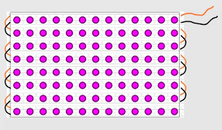
We added a new layer and drew a rectangle 160mm x 100mm and positioned it just inside the veroboard outlines. Next, a simple 5mm circle represents a UV LED, so we placed as many of those as we needed inside our eurocard outline:
A few simple wires will be used to connect all the common positive and negative rails. The flying leads can be connected to our 3v or 5v power supply (to be determined depending on the current/voltage demands of the LEDs). We may even connect the power rail through a potentiometer, to allow us to have a variable brightness on the final UV exposure unit.
We bought a load of 5mm UV LEDs from eBay which can be run at different voltages. There are loads of suppliers but all seem to offer similar bulbs. Each bulb has a 20-25 degree viewing angle. So what does this mean for us?
To get an even exposure across the entire film, we need to position our bulbs in such a way that the "spread" of light from each one overlaps with it's neighbour slightly. For example, if we simply placed our silkscreen right up against an array of UV bulbs such as this, we'd get bright spots of exposure and areas of under-exposure. We need to place the bulbs a certain distance from the silkscreen to ensure a consistent exposure.
How to calculate the distance between the bulbs and the screen for best UV exposure? Well, we're sure there's some clever way of working this out, but we did it this way:
First of all, we drew an arc of 22.5 degrees in Inkscape. We just took a guess at the radius and opted for about 25mm. Placing a few of these on top of our LEDs on the layout gave us a rough guide of how we can expect the spread of light to appear on a silk screen placed somewhere near 25mm from the LED bulb:
At 26mm from the bulb, and assuming a viewing angle of about 22.5 degrees, the UV light would still leave slightly under-exposed areas on our screen. So we scaled up the size of the arcs, until there was some overlap (the exact amount of overlap is unimportant, since we're guessing at the exact viewing angle of the bulb, and the strength or intensity of the light at the point of overlap).
After a bit of messing about, we found our optimum distance to be about 33mm
In theory, if we place our LED array in the bottom of a box and place a glass plate about 35mm above it, this should expose the entire area to UV light with no under-exposed areas. Placing our pre-prepared silkscreen (painted with UV sensitive emulsion) on top of this glass plate, and placing a pre-printed acetate sheet (with our PCB layout on it) between the glass and the silkscreen should result in a perfectly exposed screen.
Maybe.
Like a hundred other projects on this blog, we'll have to wait until we've got the bits to try it out!


No comments:
Post a Comment