Sunday, September 30, 2012
Georgia Health Sciences University uses new surgical robots
Today, robots can clean, help us communicate with friends, and even save lives. Even at universities like the Georgia Health Sciences University, doctors use DaVinci robots to operate on patients. These robots can reduce recovery time, decrease the duration of the operation, and the precision surpasses open surgery any day. All these benefits result in a better surgery. As robotics technology gets more advanced, robots like DaVinci will just keep getting better. Thanks for reading and check out the video above to see the robotic surgeons!
Friday, September 28, 2012
Inkjet printer teardown - get at those stepper motors!
At last night's BuildBrighton open evening, we set to work opening up an old HP Inkjet printer, using our favourite opening-tools - hammers and hacksaws!

We were after a few parts from inside the printer - namely the stepper motors and linear rods (that hold the print head carriage). Before setting to work with the hammer, we located which parts of the printer we wanted to avoid hitting (too hard)

It didn't take long before the plastic casing was off...

And we had hold of a feast of salvaged goodies:

Of particular interest to us was the dc motor (used to make the print carriage travel left-to-right) the nice chunky steel rod with precision made carriage (actually just some moulded plastic with brass rings that slide along the rod - no fancy linear bearings here!), the rubber paper-pickup wheels (for our future lathe project) and of course, the stepper motors (complete with pulley heads and drive belts).
We started to get to work straight away on the stepper motors. They're five-wire connections so already we're considering uni-polar steppers. To find out exactly what we've got, we drew up a table of connections, put an ohm-meter across each of the pins in turn and noted down the respective resistances across each set of pins.

We noticed that all connections to pin three were roughly half the resistance of the others (about thirty ohms). From this table of resistances we worked out that we had a unipolar stepper motor with a common "centre tap" - i,e the centres of both coils were connected together

To work out the wiring for the other coils, we had to do some trial-and-error investigating. We put power onto our centre tap (pin 3) then put a ground connection onto one of the other wires (pin5, we called this pin d). The motor energised, moved slightly and locked into place.
The idea now is to identify the other three pins, such that we can label them pin a, b, c and energise them in sequence a,b,c,d or d,c,b,a to get the motor to spin in either direction.

With pin d still grounded, we then grounded the other three pins, one at a time. Where the stepper motor moved slightly anticlockwise, we'd found our pin c. When the motor moved slightly clockwise, we'd hit upon pin a. When there was no movement in the motor, we'd grounded the (remaining) pin b.
Using this rough-and-ready approach, we successfully labelled all four pins on our stepper motor.

With the pins sucessfully identified, we replaced our bit of wire that poked at the pins, connecting them to ground with some IRF640 power FETs. These are like big chunky transistors, with a flyback diode built into them. By putting them on the ground side of the coil and activating them in the correct sequence, we managed to get the stepper motor to spin at quite a reasonable rate:
The driver chip is one of our old friends the PIC 18F2455, configured as a USB/HID device. Our custom software simply sends a "command byte" to tell the board which way to spin the motor.
252 = spin anti-clockwise
253 = spin clockwise
250 = stop spinning
249 = change the delay beween pulses.
We found with these steppers, that they ran quickly and quietly with a delay of 2ms between step pulses. We could increase this delay to slow the rate of rotation, but movement got more and more "jerky". A delay of just 1ms caused the stepper to hum without turning at all.

We were after a few parts from inside the printer - namely the stepper motors and linear rods (that hold the print head carriage). Before setting to work with the hammer, we located which parts of the printer we wanted to avoid hitting (too hard)

There's a stepper motor, tucked away in the corner of the enclosure - best go easy down there!
It didn't take long before the plastic casing was off...

And we had hold of a feast of salvaged goodies:

Of particular interest to us was the dc motor (used to make the print carriage travel left-to-right) the nice chunky steel rod with precision made carriage (actually just some moulded plastic with brass rings that slide along the rod - no fancy linear bearings here!), the rubber paper-pickup wheels (for our future lathe project) and of course, the stepper motors (complete with pulley heads and drive belts).
We started to get to work straight away on the stepper motors. They're five-wire connections so already we're considering uni-polar steppers. To find out exactly what we've got, we drew up a table of connections, put an ohm-meter across each of the pins in turn and noted down the respective resistances across each set of pins.

(Here Justin is testing the resistance between pins 1 and 5 - about 60 ohms)
We noticed that all connections to pin three were roughly half the resistance of the others (about thirty ohms). From this table of resistances we worked out that we had a unipolar stepper motor with a common "centre tap" - i,e the centres of both coils were connected together

To work out the wiring for the other coils, we had to do some trial-and-error investigating. We put power onto our centre tap (pin 3) then put a ground connection onto one of the other wires (pin5, we called this pin d). The motor energised, moved slightly and locked into place.
The idea now is to identify the other three pins, such that we can label them pin a, b, c and energise them in sequence a,b,c,d or d,c,b,a to get the motor to spin in either direction.

Here we can see our centre tap (pin3) connected to power, with pin5 grounded and pin1 at the same time.
With pin d still grounded, we then grounded the other three pins, one at a time. Where the stepper motor moved slightly anticlockwise, we'd found our pin c. When the motor moved slightly clockwise, we'd hit upon pin a. When there was no movement in the motor, we'd grounded the (remaining) pin b.
Using this rough-and-ready approach, we successfully labelled all four pins on our stepper motor.

With the pins sucessfully identified, we replaced our bit of wire that poked at the pins, connecting them to ground with some IRF640 power FETs. These are like big chunky transistors, with a flyback diode built into them. By putting them on the ground side of the coil and activating them in the correct sequence, we managed to get the stepper motor to spin at quite a reasonable rate:
The driver chip is one of our old friends the PIC 18F2455, configured as a USB/HID device. Our custom software simply sends a "command byte" to tell the board which way to spin the motor.
252 = spin anti-clockwise
253 = spin clockwise
250 = stop spinning
249 = change the delay beween pulses.
We found with these steppers, that they ran quickly and quietly with a delay of 2ms between step pulses. We could increase this delay to slow the rate of rotation, but movement got more and more "jerky". A delay of just 1ms caused the stepper to hum without turning at all.
Define CLOCK_FREQUENCY = 20
Define CONFIG1L = 0x24
Define CONFIG1H = 0x0c
Define CONFIG2L = 0x38
Define CONFIG2H = 0x00
Define CONFIG3L = 0x00
Define CONFIG3H = 0x03
Define CONFIG4L = 0x80
Define CONFIG4H = 0x00
Define CONFIG5L = 0x0f
Define CONFIG5H = 0xc0
Define CONFIG6L = 0x0f
Define CONFIG6H = 0xe0
Define CONFIG7L = 0x0f
Define CONFIG7H = 0x40
UsbSetVendorId 0x1923
UsbSetProductId 0x1694
UsbSetVersionNumber 0x1001
UsbSetManufacturerString "Nerd Club"
UsbSetProductString "USB stepper driver"
UsbSetSerialNumberString "1111111111"
UsbOnIoInGosub input_report_before_sending
UsbOnIoOutGosub output_report_received
UsbOnFtInGosub feature_report_before_sending
UsbOnFtOutGosub feature_report_received
AllDigital
Dim i As Byte
Dim spindir As Byte
Dim state As Byte
Dim dly As Word
Config PORTB = Output
Config PORTA.0 = Input
UsbStart
spindir = 0
state = 0
dly = 10
loop:
UsbService
If PORTA.0 = 1 Then state = 0
Select Case state
Case 250
Low PORTB.3
Low PORTB.2
Low PORTB.1
Low PORTB.0
Case 1
High PORTB.3
Low PORTB.2
Low PORTB.1
Low PORTB.0
Case 2
High PORTB.3
High PORTB.2
Low PORTB.1
Low PORTB.0
Case 3
Low PORTB.3
High PORTB.2
Low PORTB.1
Low PORTB.0
Case 4
Low PORTB.3
High PORTB.2
High PORTB.1
Low PORTB.0
Case 5
Low PORTB.3
Low PORTB.2
High PORTB.1
Low PORTB.0
Case 6
Low PORTB.3
Low PORTB.2
High PORTB.1
High PORTB.0
Case 7
Low PORTB.3
Low PORTB.2
Low PORTB.1
High PORTB.0
Case 8
High PORTB.3
Low PORTB.2
Low PORTB.1
High PORTB.0
EndSelect
WaitMs dly
Select Case spindir
Case 1
state = state - 1
If state < 1 Then state = 8
Case 2
state = state + 1
If state > 8 Then state = 1
EndSelect
Goto loop
End
feature_report_received:
Return
feature_report_before_sending:
Return
output_report_received:
'PC has sent us some data - use it here
i = UsbIoBuffer(7)
Select Case i
Case 249
dly.HB = UsbIoBuffer(1)
dly.LB = UsbIoBuffer(0)
Case 250
state = 250
spindir = 0
Case 252
spindir = 1
Case 253
spindir = 2
EndSelect
Return
input_report_before_sending:
'we're sending data back to the host
UsbIoBuffer(0) = spindir
UsbIoBuffer(1) = state
Return
Thursday, September 27, 2012
Say hello to the new hexbug warrior robots
The most successful hexbug ever to hit the market is obviously the nano. It's small, fun, and moves with excitement. Since Innovation First new this bug was a hit, they decided to take what was awesome and make it better. the result was the hexbug warrior. It's basically just a "weaponized" version of the nano, and each one has numerous weapons. The weapons enable each robot to duel each other in the ring. Each robot costs around $8.99 and you can pick one up at RadioShack. Thanks for reading and check out the video above them in a deadly battle!
Wednesday, September 26, 2012
Robohub, the new robotics website
With all the robotics information floating around the web, it's hard to find the best to delve into. That's why the people from Robots podcast have created robohub.org. This new site is perfect for any robot enthusiast, and I can see this becoming the next big robotics site. The site itself has four main category's, news, views, talk, and learn. News covers all the latest info about robotics technology. Views go in depth with expert views, discussions, and more. Talk is all about interviews with leading roboticists. Lastly, the learn category is dedicated to tutorials, learning materials, and other helpful things relating to robotics. Overall, I highly recommend you go and check out this site. Thanks for reading and check out robohub.org for more info.
Tuesday, September 25, 2012
Chuck-free lathe idea
We've been considering how to make a simple, but reliable chuck for a desktop lathe, but hitting a blank with both our Longworth and Spiral approaches.
After the recent BuildBrighton PCB making workshop, Matt came up with an idea. Like most half-baked ideas, we're still undecided as to whether it's a stroke of genius or a flash of madness.
What if we could do without a chuck?
To begin with, we're only going to be turning regular (round) shaped objects - mainly acrylic rod. So we don't necessarily need to grip an irregular shape and round it off, like many woodworkers do, when starting with square-section wood and turning it to make furniture legs and the like. We know we're starting off with a smooth, round shape.
So perhaps we could just have a couple of free-spinning wheels (shown in green below) and rest our stock in the "groove" formed by two wheels in close proximity:
 The piece should now spin freely in place, without any need for gripping the stock. If the wheels are placed such that a drive wheel can be introduced immediately on top of the piece, to complete an equilateral triangle, there's nowhere for the spinning stock to go.
If we turn the drive wheel (orange wheel in the diagram above) and it's in constant contact with the stock, then the piece should spin and still be held in place by the "triangle of wheels".
By spacing the green wheels further apart, or bringing closer together, we can change the height of the centre of the stock being turned, allowing us to introduce a cutting head to the right of the wheels and carve shapes out of the stock. That's the idea anyway.
Will it work?
We'll hopefully soon find out!
After the recent BuildBrighton PCB making workshop, Matt came up with an idea. Like most half-baked ideas, we're still undecided as to whether it's a stroke of genius or a flash of madness.
What if we could do without a chuck?
To begin with, we're only going to be turning regular (round) shaped objects - mainly acrylic rod. So we don't necessarily need to grip an irregular shape and round it off, like many woodworkers do, when starting with square-section wood and turning it to make furniture legs and the like. We know we're starting off with a smooth, round shape.
So perhaps we could just have a couple of free-spinning wheels (shown in green below) and rest our stock in the "groove" formed by two wheels in close proximity:

If we turn the drive wheel (orange wheel in the diagram above) and it's in constant contact with the stock, then the piece should spin and still be held in place by the "triangle of wheels".
By spacing the green wheels further apart, or bringing closer together, we can change the height of the centre of the stock being turned, allowing us to introduce a cutting head to the right of the wheels and carve shapes out of the stock. That's the idea anyway.
Will it work?
We'll hopefully soon find out!
Monday, September 24, 2012
The robotics hall of fame. Cast your votes today!
Back in January, we set up a robotics poll. After a few weeks, we got a total of ten votes, and Nao was the winner. Anyways, today I received a new Robot magazine. After reading a few pages, I saw a robotics poll that was set up by Carnegie Mellon University. If your interested in giving your favorite robot a chance at being the winner, then check out www.robothalloffame.org. Thanks for reading and be sure to cast your votes before September 30th!
More Colors For The Blender 3D Electric Car Model
My brother and I last night were on Skype for some time discussing the Blender 3D model of my electric car design. We both agreed that more colors were needed to decide what would be best in a model or the real deal. With this lengthy discussion was the idea of having a car in red, dark red, and bright yellow. With Blender 3D this is an easy task to change color but still takes a little time to get little details in the computer model to look right. Lighting plays a big part in this process along with some changes that needed my attention concerning the model itself. I did not like the original windshield that I had shown you here with the blue model of the car. The windshield just did not work for me so I spent some time with the redesign and came up with what you see here. Something that looks to be actually possible and still look good at the same time. One other change that I saw with the computer model was to have the roll bar supports showing in the design. It looks good but in reality this would take some doing to get it built into a real car. Possible but probably not easy. I like the look though and that is what counts here.
The whole process of coming up with three more colors for the computer model only took me a few hours and once again gives you a good idea of what can be done using Blender 3D software. For those of you who have just found my website here Blender 3D is a free modeling and animation software that you can download online. It has a steep learning curve to use the software but there are numerous tutorials for beginners to get you started. I had to slug through this process over 10 years ago when the software was still quite new. It has improved greatly since that time and a lot of great features have been put into the software to be able to compete with the big boys like Maya (an animation industry staple). It has been gaining ground every year since it's creation by remaining open source. This is where Joe Average like me and you can contribute ideas to the makers of Blender and actually improve on it. Great software for creative types like you and I.
So with out going any further, here are the new colors for the electric car model that I pulled together in just a few short hours time.


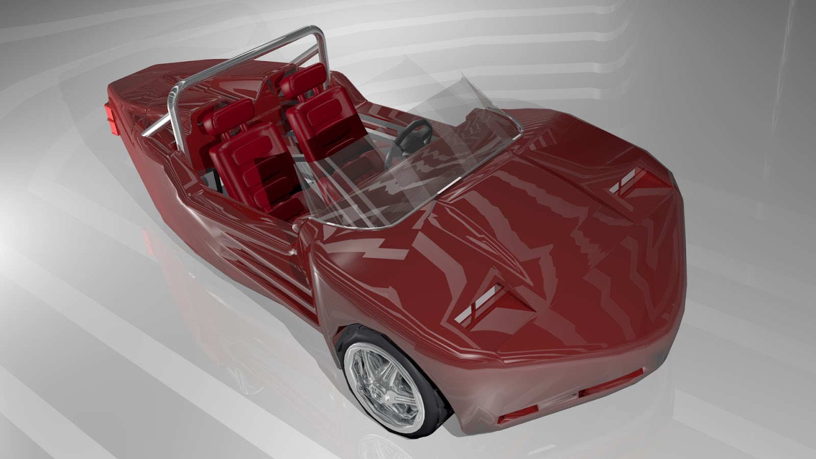
This dark maroon color is my favorite of the bunch. Very classy looking I think.


Red is always a good color also for a car but I think it needs some white accents. Stripes might be nice down the sides.


This bright yellow will surely get the attention of other drivers on the road so you are less likely to blend into traffic. Being such a small car at only 12 feet long and 42 inches tall it may not be a bad idea to go this route with the color. Also with these images I played around with different colors for the interior of the car. Easy to do with just a click of a computer button and a few tweaks to get the color the way I want it.
Fun ideas to play around with using Blender 3D. A great tool to learn and use in the creation of new concepts such as my electric car design. What's nice about this example of using the software was that I could use the model over and over again and only change the color but still get the same images again and again with out having to recreate the model each time. Much more detail can be put into the images you see here but for now this gets the message across and works for me once again to sparking new ideas farther down the road for this project and others that come up along the way. Enjoy the images.
Sunday, September 23, 2012
Test Coil, Country flag and Turbine blades
I made a test coil winder earlier and today i made one coil with 37 turns. I didn't add any varnish coat but the coil is difficult to remove from the fixture
 ... I shall make another simple jig tomorrow that will ease up removing the coil without destroying it.
"Roman" at cnczone posted a helping post in my thread about Coil winding , following are his words for everybody who need to wind the coils:
"About your coil winding jig, I have done many coils and even worked in an electrical motor shop that had a few commercial coil winders.
Suggestion 1; Put the jig on the end of a portable electric drill (with a speed control) and then it can wind automatically. A lathe is also good if it has a low speed.
Suggestion 2; You can paint the coil with varnish or nail polish every layer as you wind it, which will then be a reliable solid coil when done. However this will stick badly to your coil former. If you made the coil former from polyethelene (like food chopping board) the glue will not stick and you can make solid coils then pop them off the former. You might need a small taper on the middle round part, to slide out of the coil.
The magnetic forces on the windings will be high, so somehow they need to be set in resin or varnish. Otherwise if there is any air in the coil the windings will flex and rub because of the magnetic field and soon wear through the insulation and fail.
If putting a dry winding in resin we would put in a vacuum chamber to make sure the resin goes through the coil and no air is present. It is easier to varnish the coil as you wind it, every layer, so I would go for the polyethelene former and do that. Varnish type is not that important, quick dry nail polish is an acrylic and will be strong and bond well later when you set the hard coil into the former with resin."
I hand rotated the magnetic plates and got 1.5Volts (don't know about the RPM) with single test coil. Tomorrow i shall borrow a stroboscope and will plot a graph between RPM and Voltages. following is the formula to get estimated cut in voltages.
Required Cut in Voltages= VAC(of test coil at cut-in speed) x No. of coils/phase x1.732(multiplication factor for 3 phase)x1.414 (DC conversion factor) - 1.4V (diode drop)
The cut-in speed i shall keep around 150~200RPM. You can see pictures of furling flapper that is turned into flag of my country.

Three PVC blades 6feet each worked out by my brother one year back . The blades are big you can see pen kept on the center blade for comparison.

BuildBrighton PCB making workshop
Yesterday (Saturday) was BuildBrighton's PCB making workshop, as part of the Brighton Digital Festival.
From a worryingly quiet start, we ended up with six people taking part in yet another successful practical workshop - 100% success rate!
Over six hours, we introduced the attendees to schematic drawing using ExpressPCB (it's much simpler and easier to get going with than Eagle for anyone new to electronics/PCB layout) and their PCB layout software. A few people had brought along projects that they were working on and we helped them create PCBs for their own creations, while everyone else set about recreating the famous BuildBrighton Drawdio kit.
 (all the tools needed for making your own PCBs, including ExpressPCB software, press-n-peel blue paper, ferric chloride, a sanding block and a heavy duty laminator!)i
Sadly, the workshop was such as success and everyone was having such a lovely time that we forgot to take any more photos! But, for reference, for anyone who attended and would like to know more:
The first step was to create/draw your schematic (the bit with the little squiggles and symbols for electronic components). The most important thing to remember here is to give every component on the drawing a unique Part ID (the name can be anything, it's that part id that's referenced in the PCB layout software)
Then we drew our actual PCB layout using ExpressPCB.
File -> Link schematic to import the list of part IDs used in our circuit. A lot of people found it easier to drop symbols for all components used onto the screen before starting the layout process (menu Component -> Component Manager). Make sure that all components are drawn on the top (red) layer!
The most important thing to remember here is no crossing the lines!
In a few instances, some people ended a trace with a round pad, allowed another trace to pass "through" and started the trace again the other side, with another pad

Where a trace is continued after allowing another to "pass through" we tend to draw a connecting line on the silkscreen (yellow) layer, to act as a reminder when assembling the final board.
Once the PCB layout was complete, it was time to get on with the toner transfer.
For our workshop, we used Press-n-Peel (blue)

Toner transfer paper tends to be quite expensive, so rather than just print straight onto the blue sheet, we printed our PCB layout onto plain paper first (using a laser printer - inkjet just won't work for this!). Then cut out a piece of p-n-p blue just a bit larger, stuck it over the printed image with regular tape (shiny side down, powdery side up) and re-printed the image. This gets the PCB image onto the smallest sized bit of press-n-peel, meaning you've got plenty more left for another go!
With the image on the press-n-peel, we cleaned up some copper clad board (available from various online suppliers - eBay sometimes is a cheap source) using a fine-grit sanding block.
Sanding the board not only cleans it up (it needs to be bright and shiny and all traces of oxidation removed) it also provides a slight "key" for the toner image to stick to when transferred.
Tape the image (face down) onto the shiny copper board using paper-based masking tape, preferably cut to fit into a corner of your copper board (so it takes less cutting later). It's important not to use sellotape or similar plastic backed tape, as this will melt during the transfer process.
We used a heavy-duty laminator, but you could also use a regular household iron.
After three passes through the laminator, the image is transferred onto the copper board. Douse in cold water (carry the board by its edges, it gets very hot!) and carefully peel off the backing.

When done correctly, there should be no black traces left on the backing sheet. Check all traces carefully on the copper board. Where necessary, touch up any missing detail with a fine-tipped permanent (black) pen.
When happy with the transferred image, it's time to actually do some etching!
 Ferric Chloride (FeCl) is messy stuff. Make sure you're wearing your old clothes and get ready to clean up any spillage immediately (it stains!). We made up a small batch using hot water and about a quarter of a pack of crystals. Etching in warm solution is quicker than in cold, although the end result(s) are the same.
The Ferric Chloride solution should be a dark brown in colour. If it's pale yellow, you need to add more crystals. If it's an orange-y colour, it will probably work but will take a long time. If you're re-using old solution (that's already had a few boards etched) and it's a dark green-y colour, it's getting a bit old and you should consider refreshing it. A dark brown (which is a golden yellow colour at the edges) is the perfect strength mix.
Submerge the board and either tip the container slightly to wash the mixture over the board (large boards in a small, shallow contianer) or dip the boards in and out of the mixture (smaller boards, suspended in a tall container on bits of wire). It will take 10-15 minutes for the board to etch completely.
The copper board etches in a couple of stages and if you keep checking it regularly, you'll see:
Firstly, the board goes a very vibrant pink.
Then the edges of the board (where the copper is exposed) start to look a little bit green.
Finally, the edges of the board turn a beige colour (the natural colour of the board the copper was stuck to) and the etching continues, usually from the edges, towards the centre of the board)
When no trace of copper remains (double-check for little bits of pink between the black traces on the board) your PCB is fully etched. Congratulations!
Some people prefer to drill then clean their boards - we did it the other way around.
You can use nail-varnish remover or similar acetone-based cleaner, or simply scrub with a fine-grit sanding block until all traces of the black toner are removed and you're left with a shiny new PCB.

During our workshop, everyone successfully made their PCB, etched and drilled to a finished standard! A few brave souls even populated their boards with the Drawdio components provided - and they worked!!
All in all, another successful BuildBrighton workshop and a great day making stuff!
From a worryingly quiet start, we ended up with six people taking part in yet another successful practical workshop - 100% success rate!
Over six hours, we introduced the attendees to schematic drawing using ExpressPCB (it's much simpler and easier to get going with than Eagle for anyone new to electronics/PCB layout) and their PCB layout software. A few people had brought along projects that they were working on and we helped them create PCBs for their own creations, while everyone else set about recreating the famous BuildBrighton Drawdio kit.

Sadly, the workshop was such as success and everyone was having such a lovely time that we forgot to take any more photos! But, for reference, for anyone who attended and would like to know more:
The first step was to create/draw your schematic (the bit with the little squiggles and symbols for electronic components). The most important thing to remember here is to give every component on the drawing a unique Part ID (the name can be anything, it's that part id that's referenced in the PCB layout software)
Then we drew our actual PCB layout using ExpressPCB.
File -> Link schematic to import the list of part IDs used in our circuit. A lot of people found it easier to drop symbols for all components used onto the screen before starting the layout process (menu Component -> Component Manager). Make sure that all components are drawn on the top (red) layer!
The most important thing to remember here is no crossing the lines!
In a few instances, some people ended a trace with a round pad, allowed another trace to pass "through" and started the trace again the other side, with another pad

Where a trace is continued after allowing another to "pass through" we tend to draw a connecting line on the silkscreen (yellow) layer, to act as a reminder when assembling the final board.
Once the PCB layout was complete, it was time to get on with the toner transfer.
For our workshop, we used Press-n-Peel (blue)

Toner transfer paper tends to be quite expensive, so rather than just print straight onto the blue sheet, we printed our PCB layout onto plain paper first (using a laser printer - inkjet just won't work for this!). Then cut out a piece of p-n-p blue just a bit larger, stuck it over the printed image with regular tape (shiny side down, powdery side up) and re-printed the image. This gets the PCB image onto the smallest sized bit of press-n-peel, meaning you've got plenty more left for another go!
With the image on the press-n-peel, we cleaned up some copper clad board (available from various online suppliers - eBay sometimes is a cheap source) using a fine-grit sanding block.
Sanding the board not only cleans it up (it needs to be bright and shiny and all traces of oxidation removed) it also provides a slight "key" for the toner image to stick to when transferred.
Tape the image (face down) onto the shiny copper board using paper-based masking tape, preferably cut to fit into a corner of your copper board (so it takes less cutting later). It's important not to use sellotape or similar plastic backed tape, as this will melt during the transfer process.
We used a heavy-duty laminator, but you could also use a regular household iron.
After three passes through the laminator, the image is transferred onto the copper board. Douse in cold water (carry the board by its edges, it gets very hot!) and carefully peel off the backing.

When done correctly, there should be no black traces left on the backing sheet. Check all traces carefully on the copper board. Where necessary, touch up any missing detail with a fine-tipped permanent (black) pen.
When happy with the transferred image, it's time to actually do some etching!

The Ferric Chloride solution should be a dark brown in colour. If it's pale yellow, you need to add more crystals. If it's an orange-y colour, it will probably work but will take a long time. If you're re-using old solution (that's already had a few boards etched) and it's a dark green-y colour, it's getting a bit old and you should consider refreshing it. A dark brown (which is a golden yellow colour at the edges) is the perfect strength mix.
Submerge the board and either tip the container slightly to wash the mixture over the board (large boards in a small, shallow contianer) or dip the boards in and out of the mixture (smaller boards, suspended in a tall container on bits of wire). It will take 10-15 minutes for the board to etch completely.
The copper board etches in a couple of stages and if you keep checking it regularly, you'll see:
Firstly, the board goes a very vibrant pink.
Then the edges of the board (where the copper is exposed) start to look a little bit green.
Finally, the edges of the board turn a beige colour (the natural colour of the board the copper was stuck to) and the etching continues, usually from the edges, towards the centre of the board)
When no trace of copper remains (double-check for little bits of pink between the black traces on the board) your PCB is fully etched. Congratulations!
Some people prefer to drill then clean their boards - we did it the other way around.
You can use nail-varnish remover or similar acetone-based cleaner, or simply scrub with a fine-grit sanding block until all traces of the black toner are removed and you're left with a shiny new PCB.

During our workshop, everyone successfully made their PCB, etched and drilled to a finished standard! A few brave souls even populated their boards with the Drawdio components provided - and they worked!!
All in all, another successful BuildBrighton workshop and a great day making stuff!
Saturday, September 22, 2012
A Body For My Electric Car Model Using Blender 3D
This past week or so I have been playing with building a body for the electric car model that I just completed only a few weeks ago. This is a long and slow process to create a fiberglass body for such an interesting and detailed model. This can be tedious at times but fun at the same time. Sometimes my ideas for such a project as this I want to show off quicker and what I've found works the best for me is to create my ideas on the computer using Pro-Engineering software. This is ok but to make it a lot more interesting and polished looking I then take it a step farther and send the files to Blender 3D software to really start getting my ideas across. With Blender 3D I am able to refine my ideas of what a finished model or even a real electric car would be like. My dreams come to life using Blender 3D and if you have not learned how to use this great software yet I strongly urge you to do so. Jump in and take the plunge. Your efforts will be rewarded by being able to make your ideas come to life even if only it is on a computer screen. With this in mind here are a couple images of my idea for a body for my electric car design. Someday I hope that this vehicle will actually roll down the road. Until then these images help me get my ideas across to everyone here. Enjoy.


Friday, September 21, 2012
PIC based stepper driver controller for CNC
Here's the PIC code for our USB-HID device/stepper motor controller. Here's how it works:
Data is sent to the device through an 8-byte wide buffer. The seventh byte in the buffer is a "command byte" and (amongst other things) can be used to
The code is written for Oshonsoft PIC18 Simulator/compiler and runs on an 18F2455 PIC microcontroller
CNC drill schematic
Data is sent to the device through an 8-byte wide buffer. The seventh byte in the buffer is a "command byte" and (amongst other things) can be used to
- set the number of steps to move on the x-axis
- set the number of steps to move on the y-axis
- start the head moving
- plunge the drill
- set the backlash values for x/y axis
- set the minimum/maximum drill height
- if the head is still moving (x/y direction)
- if the drill is activated (spinning/plunging)
- if the machine is ready to receive the next command
The code is written for Oshonsoft PIC18 Simulator/compiler and runs on an 18F2455 PIC microcontroller
Define CLOCK_FREQUENCY = 20
Define CONFIG1L = 0x24
Define CONFIG1H = 0x0c
Define CONFIG2L = 0x38
Define CONFIG2H = 0x00
Define CONFIG3L = 0x00
Define CONFIG3H = 0x03
Define CONFIG4L = 0x80
Define CONFIG4H = 0x00
Define CONFIG5L = 0x0f
Define CONFIG5H = 0xc0
Define CONFIG6L = 0x0f
Define CONFIG6H = 0xe0
Define CONFIG7L = 0x0f
Define CONFIG7H = 0x40
UsbSetVendorId 0x1234
UsbSetProductId 0x1234
UsbSetVersionNumber 0x1122
UsbSetManufacturerString "Nerd Club"
UsbSetProductString "CNC drilling machine"
UsbSetSerialNumberString "1111111111"
UsbOnIoInGosub input_report_before_sending
UsbOnIoOutGosub output_report_received
UsbOnFtInGosub feature_report_before_sending
UsbOnFtOutGosub feature_report_received
AllDigital
Dim i As Byte
Dim stepsx As Long
Dim stepsy As Long
Dim dirx As Byte
Dim diry As Byte
Dim domove As Bit
Dim doplunge As Bit
Dim isdrilling As Bit
Dim booting As Bit
Dim atdestination As Bit
Dim snapback As Bit
Dim tmp As Byte
Dim tmpw As Word
Dim tmpl As Long
Dim statex As Byte
Dim statey As Byte
Dim statez As Byte
Dim zaxisvalue As Byte
Dim drillspeedvalue As Byte
Dim zaxisspeed As Byte
Dim zservoon As Bit
Dim dservoon As Bit
Dim holdzaxis As Bit
Dim timeoutcount As Byte
Dim zmin As Byte
Dim zmax As Byte
Dim drilldir As Byte
Dim feedbackvalues As Byte
Config PORTB = Output
Config PORTC.7 = Output
Config PORTC.6 = Output
Symbol coila_1 = PORTB.0
Symbol coilb_1 = PORTB.1
Symbol coilc_1 = PORTB.2
Symbol coild_1 = PORTB.3
Symbol coila_2 = PORTB.4
Symbol coilb_2 = PORTB.5
Symbol coilc_2 = PORTB.6
Symbol coild_2 = PORTB.7
Symbol zaxis = PORTC.7
Symbol drillspeed = PORTC.6
init:
booting = 1
domove = 0
doplunge = 0
atdestination = 1
statex = 1
statey = 1
statez = 0
snapback = 1
zservoon = 1
zaxisvalue = zmin 'retracted
dservoon = 1
drillspeedvalue = 90 'midpoint=stopped
zaxisspeed = 50
holdzaxis = 0
timeoutcount = 0
zmin = 150
zmax = 175
drilldir = 0
isdrilling = 0
feedbackvalues = 1
UsbStart
'wait 1 second before sending any servo commands
'(so the servo controller doesn't freak out)
WaitMs 1000
'set up a timer1 interrupt to occur every 1/20th second
'(for servo control commands- particularly motor spin speed)
'(we use this for servos)
'enable timer1 interrupts to trigger every 1ms
INTCON1.GIE = 1 'enable global interrupts
PIE1.0 = 1 'enable TMR1 interupts
INTCON.6 = 1 'enable all unmasked interrupts
INTCON.7 = 1 'enable Global interrupts
PIR1.0 = 0 'reset interupt flag
T1CON.TMR1CS = 0 'use fosc/4
T1CON.TMR1ON = 1 'turn on timer1
'enable timer0 in 16-bit mode
T0CON.T08BIT = 0
T0CON.TMR0ON = 1
T0CON.T0CS = 0 'use fosc/4
'connect to the brushless motor controller
'(it has a specific startup sequence)
drillspeedvalue = 90
'make sure the drill is retracted(~200ms)
zservoon = 1
zaxisvalue = zmin
drillspeedvalue = 90
loop:
booting = 0
While domove = 1
Select Case statex
Case 1
High coila_1
Low coilb_1
Low coilc_1
Low coild_1
Case 2
High coila_1
High coilb_1
Low coilc_1
Low coild_1
Case 3
Low coila_1
High coilb_1
Low coilc_1
Low coild_1
Case 4
Low coila_1
High coilb_1
High coilc_1
Low coild_1
Case 5
Low coila_1
Low coilb_1
High coilc_1
Low coild_1
Case 6
Low coila_1
Low coilb_1
High coilc_1
High coild_1
Case 7
Low coila_1
Low coilb_1
Low coilc_1
High coild_1
Case 8
High coila_1
Low coilb_1
Low coilc_1
High coild_1
EndSelect
Select Case statey
Case 1
High coila_2
Low coilb_2
Low coilc_2
Low coild_2
Case 2
High coila_2
High coilb_2
Low coilc_2
Low coild_2
Case 3
Low coila_2
High coilb_2
Low coilc_2
Low coild_2
Case 4
Low coila_2
High coilb_2
High coilc_2
Low coild_2
Case 5
Low coila_2
Low coilb_2
High coilc_2
Low coild_2
Case 6
Low coila_2
Low coilb_2
High coilc_2
High coild_2
Case 7
Low coila_2
Low coilb_2
Low coilc_2
High coild_2
Case 8
High coila_2
Low coilb_2
Low coilc_2
High coild_2
EndSelect
If stepsx > 0 Then
If dirx = 1 Then
statex = statex + 1
If statex > 8 Then statex = 1
Else
statex = statex - 1
If statex < 1 Then statex = 8
Endif
stepsx = stepsx - 1
Endif
If stepsy > 0 Then
If diry = 1 Then
statey = statey + 1
If statey > 8 Then statey = 1
Else
statey = statey - 1
If statey < 1 Then statey = 8
Endif
stepsy = stepsy - 1
Endif
If stepsx = 0 And stepsy = 0 Then
'set the flag to say we've arrived at the destination
atdestination = 1
domove = 0
Else
atdestination = 0
'we need a delay for the stepper to respond
WaitMs 1
Endif
'poll the usb just to keep it alive
UsbService
Wend
'important: only plunge when NOT moving!
If domove = 0 Then
If statez > 0 Then
domove = 0
atdestination = 0
isdrilling = 1
Select Case statez
'--------------------------------
Case 1 'start the drill spinning
'--------------------------------
drillspeedvalue = 255
WaitMs 100
statez = 2
'-------------------
Case 2 'moving down
'-------------------
If zaxisvalue < zmax Then
zaxisvalue = zaxisvalue + 1
If zaxisspeed > 0 Then WaitMs zaxisspeed
Else
zaxisvalue = zmax
statez = 3
Endif
'----------------------------------------
Case 3 'wait at the bottom of the stroke
'----------------------------------------
WaitMs 500
statez = 4
'-------------------
Case 4 'moving up
'-------------------
If zaxisvalue > zmin Then
zaxisvalue = zaxisvalue - 1
If snapback = 1 Then
'don't delay
Else
If zaxisspeed > 0 Then WaitMs zaxisspeed
Endif
Else
zaxisvalue = zmin
statez = 5
Endif
'-----------------------------------
Case 5 'brake (not break) the drill
'-----------------------------------
drillspeedvalue = 60
WaitMs 100
statez = 6
'-------------------------------
Case 6 'stop the drill spinning
'-------------------------------
drillspeedvalue = 90
statez = 0
WaitMs 100
atdestination = 1
isdrilling = 0
EndSelect
Endif
Endif
'poll the usb to keep it alive
UsbService
Goto loop
End
feature_report_received:
Return
feature_report_before_sending:
Return
output_report_received:
Select Case UsbIoBuffer(7)
'--------------------------------------
Case 1 'set X step count/direction
'--------------------------------------
dirx = UsbIoBuffer(4)
tmpw.HB = UsbIoBuffer(3)
tmpw.LB = UsbIoBuffer(2)
tmpl.HW = tmpw
tmpw.HB = UsbIoBuffer(1)
tmpw.LB = UsbIoBuffer(0)
tmpl.LW = tmpw
stepsx = tmpl
domove = 0
'--------------------------------------
Case 2 'set Y step count/direction
'--------------------------------------
diry = UsbIoBuffer(4)
tmpw.HB = UsbIoBuffer(3)
tmpw.LB = UsbIoBuffer(2)
tmpl.HW = tmpw
tmpw.HB = UsbIoBuffer(1)
tmpw.LB = UsbIoBuffer(0)
tmpl.LW = tmpw
stepsy = tmpl
domove = 0
'---------------------------------
Case 240 'reset the flag buffers
'---------------------------------
zaxisvalue = zmin
domove = 0
statez = 0
drillspeedvalue = 90
WaitMs 300
isdrilling = 0
atdestination = 1
'----------------------------------------------------------
Case 241 'set which values you want to read back from usb
'----------------------------------------------------------
feedbackvalues = UsbIoBuffer(0)
'--------------------------------------
Case 247 'zmin value
'--------------------------------------
zmin = UsbIoBuffer(0)
'--------------------------------------
Case 248 'zmax value
'--------------------------------------
zmax = UsbIoBuffer(0)
'--------------------------------------
Case 249 'set the z-axis step speed
'--------------------------------------
zaxisspeed = UsbIoBuffer(0)
'--------------------------------------
Case 250 'set the drill speed
'--------------------------------------
drillspeedvalue = UsbIoBuffer(0)
'--------------------------------------
Case 251 'set the zaxis servo depth
'--------------------------------------
zaxisvalue = UsbIoBuffer(0)
statez = 0
'--------------------------------------
Case 253 'plunge the drill
'--------------------------------------
statez = 1
domove = 0
'--------------------------------------
Case 254 'start moving
'--------------------------------------
atdestination = 0
domove = 1
EndSelect
Return
input_report_before_sending:
'tell the PC our current status
'(so when PC sees we're at our destination, for example
'it can move onto the next command in the script)
tmp = 0
tmp.0 = domove
tmp.1 = atdestination
tmp.2 = isdrilling
tmp.7 = booting
Select Case feedbackvalues
Case 0
UsbIoBuffer(0) = 0
UsbIoBuffer(1) = 0
UsbIoBuffer(2) = 0
UsbIoBuffer(3) = statex
UsbIoBuffer(4) = zaxisvalue
UsbIoBuffer(5) = drillspeedvalue
UsbIoBuffer(6) = tmp
UsbIoBuffer(7) = 255
Case 1
tmpw = stepsx.LW
UsbIoBuffer(0) = tmpw.LB
UsbIoBuffer(1) = tmpw.HB
tmpw = stepsy.LW
UsbIoBuffer(2) = tmpw.LB
UsbIoBuffer(3) = tmpw.HB
UsbIoBuffer(4) = zaxisvalue
UsbIoBuffer(5) = drillspeedvalue
UsbIoBuffer(6) = tmp
UsbIoBuffer(7) = 255
EndSelect
Return
preloadtimer1:
'pre-load to 15535 (65,535-50,000 where 1ms=5000)
'so this causes a timeout interrupt every 10m/s
TMR1H = 50 '216 (2ms)
TMR1L = 175 '239 (2ms)
Return
On High Interrupt
'if timer1 has rolled over (hit 65535) then
If PIR1.TMR1IF = 1 Then
'save system state/working address etc
Save System
'reset the timer1 interrupt flag
PIR1.TMR1IF = 0
'preload timer1 with a number to count to
'so that it rolls over (hits 65535) after
'2ms. As it happens, at 20Mhz, we need to
'count up to 5000 for 1ms to elapse.
Gosub preloadtimer1
timeoutcount = timeoutcount + 1
If timeoutcount > 1 Then
'send the servo position control
If zservoon = 1 Then
ServoOut zaxis, zaxisvalue
Endif
'send the drill speed control
If dservoon = 1 Then
ServoOut drillspeed, drillspeedvalue
Endif
timeoutcount = 0
Endif
Endif
Resume
CNC drill schematic
CNC drilling machine - FINISHED!
With the new path finding routines in our CNC drilling software, and changes to the firmware to allow the user to manually jog the drill head up and down to get more precise alignment during initial set-up, we're finally happy to say that our cheapo CNC drilling machine is finally complete.
Or at least, complete to a state that we're happy to release for anyone else to have a go at making their own.
The last little part of the test was making sure that the machine could drill a PCB even when placed on the cutting bed at an angle. Here's a video showing exactly that:
The drilling is accurate enough for us now (there's still a little bit of play in the x-axis, but we seem to have done enough to remove/reduce any play in the y axis, even when the bed still needs to travel up-and-down in order to correct for the board being at an angle)
Here's the final board, as drilled in the video:

The holes on the bottom-right-hand edge may not be absolutely bang on, but they're good enough to make the board usable, and are about as accurate as you could get by drilling the board by hand. The photo seems to emphasise the amount of drift - it's probably less than 0.5mm away from the centre of the hole.
Having successfully completed a cnc drill test, we put the machine away!

We reckon our machine fulfills all the criteria set in the CNC drill challenge.
It's been a long (and sometimes painful) journey, but it feels great to finally complete a project, not just to a point where it's working, but to be able to compare it to a list of criteria drawn up at the start, and to be able to tick every one off the list!
Along the way we were introduced to brushless motors and their servo-protocol control boards, created our own stepper motor control boards and our own USB-based protocol for moving them, and proved that rack-and-pinion gearing can be used just as successfully for CNCs as belt drives and leadscrews.
If we were to do the whole thing again?
Probably it'd look pretty similar. Maybe instead of a travelled bed-on-wheels we might use rails (similar to the x-axis) because there is a lot of play in the y-axis. But then again maybe not?
Any improvements?
Of course. Better stepper motors would be a great start. When energised, a stepper motor should have no movement in it at all - our steppers have 1mm-2mm of play because of the internal gearing. But then again, this does give us simple movement commands - no messing about with micro-stepping or any of that tricky stuff! We love the simplicity of the rack-and-pinion approach: belt-drives and leadscrews may be more popular, but we reckon we'd stick with ours.
The custom software is enough to make the device usable, but the protocol for sending x- and y- axis values is so simple that allow anyone else can write their own controller software. The latest firmware not only allows you to set a the number of steps to move in both x- and y- axes, but you can also now provide a "ratio" (for every three steps in x, move one in y for example). This means that if a vector line is broken down into enough parts, the machine could be modified to do simple milling - an idea that Justin from BuildBrighton is already working on!
Or at least, complete to a state that we're happy to release for anyone else to have a go at making their own.
The last little part of the test was making sure that the machine could drill a PCB even when placed on the cutting bed at an angle. Here's a video showing exactly that:
Here's the final board, as drilled in the video:

The holes on the bottom-right-hand edge may not be absolutely bang on, but they're good enough to make the board usable, and are about as accurate as you could get by drilling the board by hand. The photo seems to emphasise the amount of drift - it's probably less than 0.5mm away from the centre of the hole.
Having successfully completed a cnc drill test, we put the machine away!

We reckon our machine fulfills all the criteria set in the CNC drill challenge.
- You can load NC compatible drill files to operate the machine
- It cost less than �50 to build, completely from scratch with new (no salvaged) parts
- It's accurate to within 0.5mm (despite the dodgy cheapo stepper motors)
- The footprint is less than a sheet of A4 (in storage mode, it's about 210mm x 160mm)
It's been a long (and sometimes painful) journey, but it feels great to finally complete a project, not just to a point where it's working, but to be able to compare it to a list of criteria drawn up at the start, and to be able to tick every one off the list!
Along the way we were introduced to brushless motors and their servo-protocol control boards, created our own stepper motor control boards and our own USB-based protocol for moving them, and proved that rack-and-pinion gearing can be used just as successfully for CNCs as belt drives and leadscrews.
If we were to do the whole thing again?
Probably it'd look pretty similar. Maybe instead of a travelled bed-on-wheels we might use rails (similar to the x-axis) because there is a lot of play in the y-axis. But then again maybe not?
Any improvements?
Of course. Better stepper motors would be a great start. When energised, a stepper motor should have no movement in it at all - our steppers have 1mm-2mm of play because of the internal gearing. But then again, this does give us simple movement commands - no messing about with micro-stepping or any of that tricky stuff! We love the simplicity of the rack-and-pinion approach: belt-drives and leadscrews may be more popular, but we reckon we'd stick with ours.
The custom software is enough to make the device usable, but the protocol for sending x- and y- axis values is so simple that allow anyone else can write their own controller software. The latest firmware not only allows you to set a the number of steps to move in both x- and y- axes, but you can also now provide a "ratio" (for every three steps in x, move one in y for example). This means that if a vector line is broken down into enough parts, the machine could be modified to do simple milling - an idea that Justin from BuildBrighton is already working on!
Wind Mill Charge Controller arrived
At last i received the wind mill charge controller. It took about 15 days to reach at my door step from Hong Kong port :).. It seems very solid and i have also recieved the software CD to monitor various parameters of the wind turbine.
I also completed the furling tail flapper.


I also completed the furling tail flapper.


Wednesday, September 19, 2012
iRobot purchases Evolution Robotics for $74 million dollars
If you have heard of the mint robot, then you may know that it's developed by Evolution robotics. A few days ago, iRobot sent out a press release stating that they bought Evolution Robotics for $74 million dollars. This is also a perfect example of horizontal integration, but now it's involving the robotics industry. Thanks for reading and check out irobot.com for more info.

Tuesday, September 18, 2012
Robots performing Gangnam style!
For the past month, I have been hearing about these new "Gangnam style" videos on YouTube. It shows a Korean music artist dancing in a new way. However, since most of you visit my blog for robotics info, I decided to show a video of some robots that can do Gangnam style. Enjoy!
Monday, September 17, 2012
Bridge laying robot made from a Lego NXT kit
Ever since I got my own NXT Lego kit, I have been watching other people's projects on YouTube. I have come across maze robots, rubix cube solver robots, and even butler robots. Today, I found a robot that can lay a bridge down for itself to cross a gap. Check out the video for yourself above.
CNC lathe alternative chuck designs
After we made a sort-of successful Longworth chuck out of acrylic, we started scouring the internet for alternative chuck designs. The problem with our Longworth chuck is that while it works quite well, there's no locking mechanism.
A spiral based chuck has natural locking, just due to the friction in the system.
Last night we got busy with the laser cutter, but using MDF instead of acrylic, for the first time. The theory being that if we made a chuck from mdf, there would naturally have more friction against any moving parts, which should help aid the locking action in our chuck.
(MDF is not good stuff for laser cutting. It stinks. And fills the place with smoke!)
We made some jaws with three little pegs on the bottom. These will sit inside the curves of a spiral.

The jaws have little "plates" slotted into them at 90 degrees, which slide inside the larger of the two cutouts

The spiral is mounted onto the plain disc. The jaws also sit on top of the spiral such that the three teeth sit between the curves of the spiral.

By mounting the slotted pieces over the jaws, we can restrict their movement so that as the spiral turns, the jaws move in and out, along their slots

The final sprial-based chuck assembly

The idea is that the working stock can be inserted into the chuck and pass right through it, the spiral disc on the back is turned, and the jaws slide along their grooves and clamp the work piece to stop it slipping when the chuck is spinning.
So, does it work?
Erm. No.
Not this version anyway.
Maybe MDF is too, erm, grippy. Or maybe the spiral isn't regular all the way around. Or maybe the design just doesn't work. The theory should be sound - it's how commercial chucks are made anyway. But perhaps we're now seeing why they sell for �30-�40 each and you don't see many made out of cheap materials for a couple of quid at the local Poundstretcher store!
Subscribe to:
Comments (Atom)