Here's a video showing the fuzz face effect "pedal" working with a Peavy Raptor guitar and miniature Marshall amp.
There's a definite difference between "clean" and "distorted" sounds and we're keen to say that the whole thing works well. The only thing is, after trying out our board, Jason from BuildBrighton turned up and asked us to try out his design - and his works even better!
So we've ended up with two types of effects pedal. Our latest design is more of an "overdrive" distortion effect, whereas Jason's is very much more "fuzzy" - more reminiscent of the original FuzzFace.
(check out the video jump at about 0:44 where the video was paused while we swapped out "our" pedal for Jason's)
Thursday, May 31, 2012
Now my Sensor has four eyes
Here is the 4-LDR version of the sun-tracking sensor with on-spot adjustment using four potentiometers. The four LDRs improves the field of view of sensor. The micro-controller programming has been changed and tested under wide conditions of lighting and its working great.
So why i used the potentiometers? Because the all the 14 LDR's in my hand provided me different readings in dark and extreme light conditions. Only two LDR's matched together and for the rest i was getting the calculated resistors values 2.5K and 2.8K which are not standard values resistors. So i came up with potentiometers where i can adjust them to get the precise resistance. Now all the LDR's can be matched with these variable resistances and the sensor will give me perfect results. I will lock the pots once adjusted.
Now by change in microcontroller programming i shifted the timing interval control from the firmware to the hardware. Now the user can select the sense/react timing of the sensor with a single potentiometer and can change the movement of panels from real time up-to 15minuts delay. Real time means the panel sensor continuously track the sun and command the motor to move. I will set this for 10minutes for myself i.e. After each 10minutes the tracking sensor will start to move the panel toward the sun.
Wednesday, May 30, 2012
Why MPPT Charge controller?
Maximum Power Point Tracking gives 10-30% more energy from the solar panels. These controllers are connected between the solar panel and batteries like any charge controller, but sophisticated electronics allow the controller to operate the solar panel at its most efficient voltage, resulting in significant gains in power.

When you connect this panel to your batteries with a conventional charger, the panel will operate at the battery voltage, say 12.6V. At this voltage, the panel won't generate significantly more current than at 17V, and the total output will be less than 40 Watts!
MPPT controller will let the solar panel run at its most efficient voltage, extract the most power possible, and charge the batteries at their voltage, with almost no loss. This way, a 50 Watts power can be received from the 50 Watt panel, a 25% gain over the conventional controller in the example above!
MPPT controller extracts the most power possible from the panel in nearly any condition: hot or cold temperatures, different light levels, partially shaded panels; it even takes wiring losses into account. The actual power gain will vary with conditions, and may be anywhere from 0-40%, with 10-30% being typical. Highest power gains come with discharged batteries, cold temperatures, and lots of light.
When 50 Watts isn't 50 Watts
As an example, consider a 50-Watt panel. The panel will typically be rated for full output power only at a particular voltage, say 17V, at which it will produce a little less than 3 amps.
When you connect this panel to your batteries with a conventional charger, the panel will operate at the battery voltage, say 12.6V. At this voltage, the panel won't generate significantly more current than at 17V, and the total output will be less than 40 Watts!
MPPT controller will let the solar panel run at its most efficient voltage, extract the most power possible, and charge the batteries at their voltage, with almost no loss. This way, a 50 Watts power can be received from the 50 Watt panel, a 25% gain over the conventional controller in the example above!
MPPT controller extracts the most power possible from the panel in nearly any condition: hot or cold temperatures, different light levels, partially shaded panels; it even takes wiring losses into account. The actual power gain will vary with conditions, and may be anywhere from 0-40%, with 10-30% being typical. Highest power gains come with discharged batteries, cold temperatures, and lots of light.
Tuesday, May 29, 2012
More accurate and Sensitive Suntracking Sensor
I have replaced the 10K resistors with more precise 3.2K resistors at the output of the LDR's to analoge pins of microcontroller. These resistors are calculated for the available LDR's.
Following Formula was used:
LDR resistance(Ohms) = SQRT ( Rdark x Rnoon)
Where Rdark = Resistance of the LDR in night (No light condition) =247 Ohm
Rnoon= Resistance of LDR at high noon (direct under the sunlight) =39000Ohm
LDR resistance = SQRT (247 x 39000)
= 3101 Ohm = 3.1 ohm
=3.2 is the nearest available resistance
Here is the spreadsheet version:

and a short video after 10K resistance replacement with 3.2K.
Monday, May 28, 2012
Guitar effects pedals
In preparation for the Mini Maker Faire in Brighton in September, we're busy designing and prototyping tiny guitar effects pedals which can be embedded behind a scratchplate.
As this involves hacking an actual instrument, it seems only sensible to keep track of where we've started from (if only so we go back to it, in the event of something going really wrong!)
The ideal starting point is not necessarily the wiring we start with - even really expensive guitars (for us, anything over about fifty quid is a really expensive guitar) can sometimes have quite shoddy wiring. So we're going to start with shielded wiring, to keep any hum and noise introduced by our effects "pedals" to a minimum.
Here's a typical three-pickup setup with shielding - note that the ground plane should be extended to the underside of the scratchplate, the tone and volume pot bodies and, if possible, the entire inside of the electrics cavity:
Shielded Wiring for Stratocaster guitar
Sunday, May 27, 2012
My Sun-tracker is Alive
Here is a short video of sun-tracker in working condition. It took my sunday to find out the weired behavior of sun-tracker. I found out two 10K resistors were the culprit on the PCB. I just removed them from the PCB and installed them directly on the sensor Analogue input wiring. My next goal is to make a pretty weather proof enclosure for the sun-tracker and electronics panel box.
My old video of sun-tracker testing:.
The latest video of my sun-tracker.
My old video of sun-tracker testing:.
The latest video of my sun-tracker.
Saturday, May 26, 2012
Out With The Old...... In With The New!
It's been a busy couple of weeks here at the Tinker's Workshop. I thought it best to finally get a new post out on what has been happening and what is planned for the coming weeks. I have been busy with a large project here at home that has turned into a chain reaction of projects as most people know can happen. For some time now I have been wanting to replace the carpet in my bedroom and repaint the room at the same time. This in turn called for the removal of a well cared for king size water bed which because of its weight had messed up the position of the closet in the bedroom. The bed weighed close to 2000 pounds and had managed to shift the closet away from the back wall of the bedroom. This I corrected with some help from a close friend and have now painted the bedroom and am waiting for the new carpet to be installed. So now on to the fun part of this project.

The current project I am now working on is to build a new bed to replace the water bed. I no longer want that much weight on the floor and so I've decided to build a queen sized platform bed instead of the over sized, overweight king sized water bed. This will be lighter on the floor and make more room in the bedroom too. The headboard of the water bed is solid oak and is to nice to discard and so that is where I started this project.
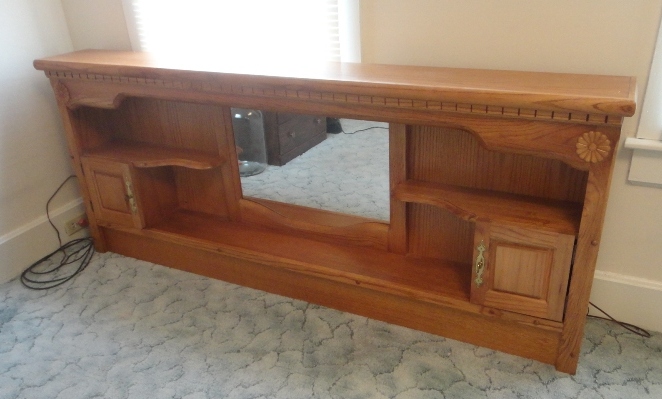
With this in mind I had to design a new platform bed using the king sized headboard yet still reduce the size of the new platform bed to a queen. This is what I came up with.

The new platform bed will use a setup very similar to the water bed as it will have a base that the mattress and mattress deck will sit on. A couple of things had to be addressed here in this project as the headboard is set up for a king sized bed and the mattress is a queen. Also the headboard could not sit directly on the same platform as the mattress as it would be to low to be usable. I designed a headboard riser that would straddle the platform so that the width difference from a queen to a king sized bed could be used along with raising up the headboard to a correct height.

The headboard riser will be made from oak along with the mattress rail (shown in gray) that will rap the deck and deck frame. The deck frame base will be made out of 2 x 8's and the deck frame out of 2 x 4's. Both made from pine. The deck is half inch plywood. All of the parts for the new bed now have been cut and being as photos of a pile of wood is not that interesting I will hold off with taking more photos of the project until it starts taking shape.
I was also concerned with the height of the bed mattress once the bed was completed as I thought it might be to low. This turned out to be no big problem as the mattress is 12 inches thick and the total height will be 24 inches tall. Very good news for the project. I will post further photos in the coming weeks as progress is made on this project.
Thursday, May 24, 2012
Vacation, no posting
As of today, I will not be posting for two weeks. However, after my vacation I will. Thanks!
Basic Wah Pedal
As part of a series of up-and-coming BuildBrighton workshops, and in preparation for this year's Mini Maker Faire we're busy putting together some simple effects "pedals" that can be put together inside a guitar, to provide onboard electronics.

The beauty of this simple design is that it uses a single 500K linear potentiometer to achieve the wah-wah sound. Which means we can do a lot with this design when it comes to "hacking" up our guitars later. For example, it could be replaced with a digital pot and hooked up to a microcontroller (such as a PIC or Arduino) for all kinds of funky fun!
We've already started work on a number of fuzz-face (distortion pedal) variants.
This time it's the original Cry-Baby Wah effect that we're looking to emulate. In fact, this circuit design is quite a bit simpler than the Dunlop version, but is perfect for what we're trying to acheive - a simple, workable circuit to act as an introduction to gutiar electronics. Here's the circuit schematic:
And the PCB layout:
Wah Pedal PCB
(as ever, print onto A4 at 100% no scaling for a press-n-peel/toner-transfer-ready image for etching your own)
(as ever, print onto A4 at 100% no scaling for a press-n-peel/toner-transfer-ready image for etching your own)
This is how the final PCB should be assembled:

The beauty of this simple design is that it uses a single 500K linear potentiometer to achieve the wah-wah sound. Which means we can do a lot with this design when it comes to "hacking" up our guitars later. For example, it could be replaced with a digital pot and hooked up to a microcontroller (such as a PIC or Arduino) for all kinds of funky fun!
Wednesday, May 23, 2012
Meet Emily, the robotic lifeguard
As we all know, summer is right around the corner. This mean that pools will be opening up, and what do pools need? Lifeguards. However, one beach in Rhode Island is using something a little different. They call it Emily, and it's a red robotic lifeguard. Even though it's a lifeguard, its not humanoid. It's just a red floating robot with a high powered propulsion system. The makers of this robot aim to help conscious people in distress using this RC robot. The reason the person has to be conscious is because they have to grab on to the robot to be rescued. Thanks for reading and check out the video above to see it in action!
Calculating Energy efficient Tilt Angle for Solar Panel
As I have already discussed in the previous post that i am adding single axis tracking to my solar panel and the Altitude angle (Tilt angle) shall be adjusted in Summer and Winter to get the maximum efficiency out of the solar panels. Here are the Rule of thumb for best tilt angle.
SEASON------------------- ANGLE TILT CALCULATION
Winter -------------------- (Latitude x 0.89) + 24 degrees
Summer ------------------- (Latitude x 1.05) - 24.3 degrees
Spring & falls -------------- (Latitude x0.98) - 2.3 degrees
Pakistan resides in Northern hemisphere so the Solar panel should be toward the TRUE SOUTH. The Tilt angle is calculated from the Horizon.
Example:
City : SADIQABAD, PAKISTAN
Latitude (from google) : 28.1700 N
Tilt Angle for Winter= (28.17 x 0.89) +24 degree = 49.07
= Say 49 degree from horizon or (90- 49 = 41 degree) from the vertical
Tilt Angle for Spring & Fall= (28.17 x 0.98)-2.3 = 25.306
= Say 25 degree from horizon or (90- 25 = 65 degree) from the vertical
Tilt Angle for Summer= (28.17 x 1.05) -24.3 degree = 5.27
= Say 5 degree from horizon or (90-5 = 85 degree) from the vertical
As these solar panels shall be installed in Karachi so:
City : KARACHI, PAKISTAN
Latitude (from google) : 24.8508 N
Tilt Angle for Winter= (24.8508 x 0.89) +24 degree = 46.11
= Say 46 degree from horizon or (90-46 = 44 degree ) from vertical
Tilt Angle for Spring & Fall= (24.8508 x 0.98)-2.3
= Say 23 degree from horizon or (90-23= 67 degree) from vertical
Tilt Angle for Summer= (24.8508 x 1.05) -24.3 degree = 1.79
= Say 1.8 degree from horizon or (90-1.8=88.2 degree) from vertical

Monday, May 21, 2012
ICRA 2012 Robotics Video
This year ICRA (international conference for robotics and automation) had a lot of stands with some pretty amazing robots. Some stands showed off small robots and some showed of humanoids. However, my favorite was the one the had a Darwin robot riding a roomba. If you would like to see these robots then check out the video above and thanks to IEEE Spectrum for putting together the video!
Saturday, May 19, 2012
Friday, May 18, 2012
Thursday, May 17, 2012
SimpleBotics SimpleBot Kit
Today I am proud to announce the first kit from SimpleBotics. Even though it's a kit it will not be for sale any time soon. The reason is because we are still trying to develop a better design for the bot and a better container. The video above shows the "commercial" for the kit. Thanks for reading and I hope you enjoy the video!
Wednesday, May 16, 2012
New robot can juggle two balls in mid air
It's been a while since a new high speed robotic arm has been introduced. However, now there's one that can juggle. Developed by Takahiro Kizaki and Akio Namiki in Japan, this bot is capable of juggling two balls at a reasonable speed (remember that this is a robot, not a clown). The robotic arm is equipped with high speed cameras, a clever arm design, and dexterous fingers. The cameras track the ball movement and then send data to the arm and fingers so the bot can catch the ball and throw it up again into the air. The last time I saw a robot like this, it was flipping a pen or bouncing a ball. Although those were interesting, it seems that this is a little by more advanced. Thanks for reading and check out the video above to see it juggle!
Updates on Control module and Panel Support Structure
Micro-controller modules are completed .

 Solar panel structure with single-axis sun tracker installed. I have used one Car windshield motor (Rs.700), motorcycle chain sprockets set (Rs. 450) and a second-hand car wheel hub (Rs. 1600) to make a single axis tracking hardware.


The structure material ,assembling and painting cost was around Rs.8000.
 I have also purchased 60V 10amp MPPT charge controller (Rs.8750), However, i am seeking to purchase 60Amp 160V MPPT charge controller (TS-MPPT-60 ) through credit card from America as its not available in Pakistan.http://www.morningstarcorp.com/en/tristar%20mppt It will cost me around 550 US dollars including taxes/duties.
purchased 02 Lead Acid batteries FB make 220AH. Cost me around Rs.24000. I preferred FB because the maintenance free deep cycle batteries are quite expensive and the market is full of poor quality Chinese batteries. Later on i shall discuss on this.


The structure material ,assembling and painting cost was around Rs.8000.

purchased 02 Lead Acid batteries FB make 220AH. Cost me around Rs.24000. I preferred FB because the maintenance free deep cycle batteries are quite expensive and the market is full of poor quality Chinese batteries. Later on i shall discuss on this.

Tuesday, May 15, 2012
Robot reviews #1
Here is a list of videos I have out together. Every single video listed is a review video on a specific robot. This is just to help any consumer out there that are thinking of buying a particular bot. Enjoy!
1.
2.
3.
4.
1.
2.
3.
4.
Monday, May 14, 2012
Read this if you hate mowing your lawn
There's robots for cleaning your gutters, floors, and windows. We even have robots that make us things. However, now we have Robomow. This bot doesn't do any of that, instead it lives up to it's name, and mows your lawn. It has has a wide variety of sensors which includes, lift sensors, tilt sensors, and bump sensors. Robomow is also electric so you don't have to worry about using gasoline and it's Eco friendly. Overall, I think this bot is very useful, but it does cost around $2,000. Thanks for reading and be sure to check out the code above to see it in action!
Sunday, May 13, 2012
Why Single Axis Sun Tracking?
After successful completion of the DC Motor controller , it is time to make the Heart of the control circuit. I have recently completed the AVR based Single Axis micro-controller circuit for Azimuth tracking of the sun.
Using dual axis solar tracking is a good idea but controlling the Altitude motor with respect to sun has very little benefit as compare to Azimuth control.Let us see the following figures for explanation:
The position of the Sun in the sky relative to an observer on Earth is defined by its altitude angle a (solar elevation angle) and its azimuth angle ?. The sun moving from East to West and the this angle we call it Azimuth Angle. The sun daily cover this Azimuth Angle. However, The Altitude Angle of the sun is changes throughout the year (seasonal motions) with a very little increments during the year days.This altitude angle is 46 degrees north-south over the period of a year. In winter the sun is more toward the Southern side and Altitude angle is small . Whereas in the summer the Altitude angle is on the extreme and sun is just traveling at the top of our head;)..


 A recent review of actual production statistics from southern Ontario suggested the energy difference between the single-axis tracker and dual-axis tracker was about 4% in total, which was far less than the added costs of the dual-axis systems. This compares unfavorably with the 24-32% improvement between a fixed-array and single-axis tracker. This is the reason I prefer to use Azimuth control of my solar panels.
Here is the micro-controller(ATMEGA328P) based single axis Azimuth control circuit with East-West limit switches. In future i shall explain how will this work.

Using dual axis solar tracking is a good idea but controlling the Altitude motor with respect to sun has very little benefit as compare to Azimuth control.Let us see the following figures for explanation:
The position of the Sun in the sky relative to an observer on Earth is defined by its altitude angle a (solar elevation angle) and its azimuth angle ?. The sun moving from East to West and the this angle we call it Azimuth Angle. The sun daily cover this Azimuth Angle. However, The Altitude Angle of the sun is changes throughout the year (seasonal motions) with a very little increments during the year days.This altitude angle is 46 degrees north-south over the period of a year. In winter the sun is more toward the Southern side and Altitude angle is small . Whereas in the summer the Altitude angle is on the extreme and sun is just traveling at the top of our head;)..


Here is the micro-controller(ATMEGA328P) based single axis Azimuth control circuit with East-West limit switches. In future i shall explain how will this work.
Thursday, May 10, 2012
Nao Next Gen. Voted best robot on our robotics poll
If you remember the post I did a while back on the robot poll, then you already know that it included Asimo, Nao, Nao next gen, Kismet, Aibo, RoboBrrd, and roomba. Anyways, a few days later and the poll received 10 votes, and out of all those votes Nao next gen. got the most. So if your a fan of this robot ten give yourself a pat on the back because this bot has one the contest!
Wednesday, May 9, 2012
A Video Camera Mount For Your Car For Less Than $20.00!
Today I completed another small project that has been in the back of my mind for some time now. I've always wanted to take video in my Mini Cooper while cruising down the road. That's what today's project is all about.


These two photos show the wooden parts that were cut out on my CNC machine for the camera mount. This could also be made using a band saw or scroll saw and a drill press just as easily.


In these two photos you will see the remaining parts that are needed for the video camera mount. There are two pieces of 3/4" poplar wood, two 1/4" x 3" bolts, four washers, two lock washers, two wing nuts, a 1/4" x 1" bolt and washer and a quick connect mount for the video camera. The two small grooves in between the two horizontal arms will located the mount securely when it is put into the car for use. The three inch bolts and related hardware squeeze the two wooden part together to create a strong simple mount that is as easy to use as it is to create.

Here is a good shot of the video camera mount located on the vertical posts that secure the headrest on the passenger front seat. The seat needs to be in a near vertical position so the video camera is not pointing upward toward the roof. I did a trial video using the mount on the passenger seat but found that I liked the drivers seat video better. As long as the roads are fairly smooth the video turns out very well. Check out what I shot today for yourself.
Click the YouTube button for a bigger view of the video.
Tuesday, May 8, 2012
The Bissel SpotBot, your pet's biggest pet peeve
If your pet causes accidents on your carpet then this bot is perfect for you. No more using your hands and knees to do all the work. SpotBot is here to help. Using it's powerful suction power, water, cleaning solutions, and fast spinning brushes, it's able to lift the toughest stains right out of your carpet. All you have to do is click a button to run a preprogrammed cleaning cycle, and the bot will do the rest. So if you hate cleaning up after your pet, then pick up a SpotBot today for only 140 USD. Thanks for reading and check out the video demo above to see it tackle some pet stains.
Basic4Android
One thing we've been keen on over the last 12 months or more, is making our own USB devices. These can be anything - we've made miniature instruments and servo controllers amongst other things, but the idea that you can create a device, plug it into a PC and it just works has been really exciting.
Out in the real world - not Nerdland - the rest of the world is busy getting on with mobile phones and tablets and cool things like that. And leaving us PC lovers behind as we look so archaic, sitting hunched over a notebook/laptop in the local coffee shop. The cool kids are too busy swooshing and swishing on their touch screens to worry too much about a few motors chained to piece of rapidly-becoming-obsolete piece of technology!
So we've had a bit of a change of heart here at Nerd Towers recently.
Rather than trying to continue denying mobiles and mobile computing, we're slowly learning to love it. By which, of course we mean, slowly learning to love Android (installing iTunes on a PC is akin to pouring cold tea down the back of the air vents, shudder, Apple, shudder). But developing for Android means getting messy with Java.
Unless you're already quite proficient with Actionscript (AS3) - then haXe is probably a great place to start. But haXe libraries are pretty limiting. We've not found anything that, for example, allows you to communicate with the USB port. So once again we set off looking for a development suite that would compile for Android, and give us access to the USB stack.
Step forward Basic4Android.
Not only is this a brilliant IDE, offering VB-style syntax and a familiar looking environment (you even hit F5 to compile and run your code for goodness sake!) it also compiles to native Android code - so no pesky AIR runtimes and making your apps incompatible with a large share of the market (AIR only runs on devices with ARM7 or better processors - most mid-range phones are still shipping with ARM6 in them).
And the best thing? USB support!
So far, we've only got a simple "hello world" app working, but it's a start.
But already Basic4Android is looking to be quite a powerful bit of kit that could really kit-start some interesting ideas (a bit like Oshonsoft Basic did for our PIC microcontrollers). It's so great, in fact, that the author is offering a special deal for all of us:
If you like the Basic4Android software, you can buy it from http://www.basic4ppc.com/
And we'll get a year's worth of free support and upgrades. So everyone benefits! But no-one more than you - when you've compiled and released your first app, who knows where it could lead.......
Out in the real world - not Nerdland - the rest of the world is busy getting on with mobile phones and tablets and cool things like that. And leaving us PC lovers behind as we look so archaic, sitting hunched over a notebook/laptop in the local coffee shop. The cool kids are too busy swooshing and swishing on their touch screens to worry too much about a few motors chained to piece of rapidly-becoming-obsolete piece of technology!
So we've had a bit of a change of heart here at Nerd Towers recently.
Rather than trying to continue denying mobiles and mobile computing, we're slowly learning to love it. By which, of course we mean, slowly learning to love Android (installing iTunes on a PC is akin to pouring cold tea down the back of the air vents, shudder, Apple, shudder). But developing for Android means getting messy with Java.
Unless you're already quite proficient with Actionscript (AS3) - then haXe is probably a great place to start. But haXe libraries are pretty limiting. We've not found anything that, for example, allows you to communicate with the USB port. So once again we set off looking for a development suite that would compile for Android, and give us access to the USB stack.
Step forward Basic4Android.
Not only is this a brilliant IDE, offering VB-style syntax and a familiar looking environment (you even hit F5 to compile and run your code for goodness sake!) it also compiles to native Android code - so no pesky AIR runtimes and making your apps incompatible with a large share of the market (AIR only runs on devices with ARM7 or better processors - most mid-range phones are still shipping with ARM6 in them).
And the best thing? USB support!
So far, we've only got a simple "hello world" app working, but it's a start.
But already Basic4Android is looking to be quite a powerful bit of kit that could really kit-start some interesting ideas (a bit like Oshonsoft Basic did for our PIC microcontrollers). It's so great, in fact, that the author is offering a special deal for all of us:
If you like the Basic4Android software, you can buy it from http://www.basic4ppc.com/
Put in the voucher code - coxvau - and you'll get a massive 50% off!
And we'll get a year's worth of free support and upgrades. So everyone benefits! But no-one more than you - when you've compiled and released your first app, who knows where it could lead.......
Low Cost DIY DC Motor Controller for AZIMUTH Control
Recently i designed a low cost DC motor controller using relay, MOSFET IRL540N. This circuit can handle up to 5A current and i shall use this for AZIMUTH control of my Solar Panels. I shall use wind power shield motor to run on this circuit.

This circuit is under testing with micro-controller and doing fine so far.

This circuit is under testing with micro-controller and doing fine so far.
Monday, May 7, 2012
The most realistic transformer robot yet
I have seen some pretty neat transforming robots, but this one tops them all. Not only does it look like a car when it's in disguise, but it transforms into a robot at a reasonable speed. It's not to slow, and when's it's in robot form it gives off a good look and appeal. I guess these bots will just keep getting better and better each year. Although, It's going to be a while until we get one that Michael Bay approves of. Thanks for reading and check out the video above to see it in action!
Friday, May 4, 2012
TelepresenceRobotics.com, a site dedicated to telepresence robots
We�re excited to guest post today � thank you, Morgan! Be sure to check out Morgan�s guest post on our blog: www.telepresencerobots.com/blog.
We�re a brand new company aiming to serve as an information source for telepresence robots. Our website, www.TelepresenceRobots.com, launched last month. We provide a platform for registered users to rate and review telepresence robots, a forum for users to discuss the robots, a comparison chart for users to view product specifications, and a blog for users to receive the latest industry news.
Telepresence robots are becoming more widely used in offices, hospitals, and schools. Companies use them to attend meetings or conferences and to travel to facilities that are difficult to reach. Watch Google co-founder Sergey Brin use Willow Garage�s Texai robot here! Boston Children�s Hospital has started sending VGo telepresence robots home with post-op patients. Doctors and nurses use the robots to monitor patients at home while they recover. Some professors at universities even use telepresence robots to teach classes, but that�s not the only way they�re being used at schools. Disabled students find the robots useful as well. A student in Knox City, Texas uses a VGo robot to attend his classes and continue his education because he is too unhealthy to physically attend school.
Purchasing these robots, though, can be a tough decision. They�re expensive, so prospective buyers want to make sure they�re making the right purchase. With all of the different robots out there, it can get overwhelming and confusing to decide on one. We hope to alleviate some of that stress. Buy reading the reviews and using other features on our site, businesses, hospitals, and schools can decide which robot best fits their specific needs.
Right now, our site features the MantaroBot TeleMe, Anybots QB Robot, PeopleBot P3-DX, and MantaroBot Classic. If you want to contribute a review to our site, click here!
If you want more information on telepresence robots, follow us on twitter @telerobotic to receive industry news and updates. Check back on our site, , for new blog posts, forum discussions, and reviews.
Thank you, Morgan, for hosting us!
Thursday, May 3, 2012
Lego NXT cleaning robot
As you may know by now, HomeBot is in the making. With that being said, I did some tests today to see which cleaning methods work the best. In the video above it shows one of the tests using my NXT robot I got back in 2007. This robot uses a simple program to avoid obstacles using an ultrasonic sensor, and it tackles dirt using a swifter wet jet pad. However, HomeBot I'm planning on using a micro fiber cloth. Thanks for reading and I hope you enjoy the video above.
Wednesday, May 2, 2012
The Second Steadicam Is Completed!
This past week I was thrilled to finally find in my mailbox the last piece that I needed for my second Steadicam that I started work on in mid April. This critical piece was the adjustable mounting plate for the video camera. Without it I could not complete the build of my new design. For those of you who do not know what a Steadicam is or what it does for video I will clue you in. This device takes the roughness out of video being shot while hand holding a video camera. It was first used and developed for the movie "Rocky". Since that time you have seen the end result of this device in scores of movies. Most commonly used where a camera is following or leading an actor down the street and the director wants a smooth flowing shot without the camera bumping up and down from the cameraman's movements. These professional devices are VERY expensive and just now have started to show up for the amateur videographers like myself. So with that in mind I decided to build my own Steadicam this being the second design.

With any new design there are always bugs that need to be worked out of it. This design was no exception to that rule. The picture above shows the upper mounting portion of the acrylic arm as I first designed it. It looks good but that's about as far as it goes. It simply did not work when mounted to the adjustable "C" shaped slider video camera rail. I could not get the arm to balance and so a redesign was called for. The first arm being made out of fiberglass did not have the mounting hardware that you see in this shot. This in turn caused the arm to be mounted further rearward on the slider rail. This also caused an interference problem that would not allow me to make proper adjustments to balance the Steadicam.
What I did to correct this was redesign the original spacer mount that you see here with a modified spacer that has an extension on it to allow clearance for the balance arm. Once this was done I cut it out the new part on the CNC machine and with a bit of sanding was ready to mount it. The original fiberglass arm on the first design was narrower and could be mounted on to the slider rail without the use of a spacer.


Here are a couple of shots of what the new upper mount looks like in place on the Steadicam. The extension on the new mount allows for an additional clearance both vertically and horizontally as the slider is adjusted to balance the Steadicam with the camera mounted to it.

Here is a good shot of me holding the new design which gives you a good idea of the size of the Steadicam. This completed arm took around two hours to construct using my CNC machine to cut out the balance arm parts. Then came sanding, polishing, and assemble. This is a vast improvement over the fiberglass design as it took around eight hours to build over a weeks time. The cost is higher on this arm due to the material used but in the long run will be much easier to fix should something catastrophic happen to it. (I don't even want to think about it!)
For a larger view press the Youtube button.
Here is a little video that I put together this morning showing you the difference in what the Steadicam can do for your camera work. Keep in mind here that I have only had about a half hour of practice using this new Steadicam so I am no expert when using it yet. But just with what I have shot here is a vast improvement over the video shot without using it.
For those interested in the numbers..... The original fiberglass design cost around $40 to build. This new design is closer to $80 to build. Both turned out well and both had their advantages and disadvantages in the building of them. I for one like the new design simply because of the ease of construction, less build time, and easier repair. If you had to repair the fiberglass design or replace it due to major damage it would take another week to build a new one. This design you could salvage all the good parts and only replace what needed to be to make it work once again. A lot less time to do so. All in all it will make a nice addition to my video camera equipment.
Tuesday, May 1, 2012
Mint Plus, from Evolution Robotics
There's nothing better than a mint robot that can clean your hard wood and tile floors. Except for the all new Mint Plus. Mint Plus offers better cleaning on a single charge. With a bigger battery, better navigation, and cleaning system, it's ideal for any person that hates cleaning floors. Unlike its competitor, Roomba, this robot only costs $299.99. Thanks for reading click here if you are interested in purchasing one!
Subscribe to:
Posts (Atom)