Updates have been few and far between recently. But that's because of some exciting news (well, it's exciting for us anyway). After six months in Wales, we're heading back to the digital centre of the UK - sunny Brighton!
That means hooking up with the cool kids at dotbrighton and BuildBrighton again, working on some cool group projects, as well as advancing our haXe development and mobile games learning.
Check back for updates as we put all this moving business behind us (arranging visits to view properties, travelling up and down the country, loading and unloading equipment as well as moving houses) and get back to nerding about and making more cool stuff!
Saturday, March 31, 2012
Friday, March 30, 2012
Plexiclock Build Continues..... Getting More Interesting!
I spent the day yesterday in Davenport Iowa at the QC Co-Lab maker space working on the next step of the plexiglass clock project. This is the progress that I made with my efforts.


In these three photos you can see the 27 plexiglass (clear acylic plastic) numbered blanks that make up the guts of the clock. In my previous post I engraved these parts and them cut them out using the CNC machine in the workshop. At the Co-Lab I then sanded all the edges of these parts smooth and then took a butane torch and heated the fogged edges. When you cut acrylic plastic and or sand it the clear plastic will fog. When you heat these edges with a torch they become clear once again. This will help make the numbers brighter when the LED lights shine through them.


These two photos give you a good view of the numbered blanks once they have been mounted between the two vertical supports. This was a real trick to get all 27 blanks lined up to with the slots in the mating side of the assembly. It took me at least a half hour and a lot of fiddling to get all the parts in correct position so it all slid together the way I had designed the assembly. With the top and bottom parts not yet mounted the light shining through the assembly allows a nice view of the numbered blanks that are in the assembly.

Here is a good view of the clock inner assembly with the top and bottom plates temporarily taped in place so fiber-glassing could be done.


These last two photos show the fiber-glassing starting to be done to hold the entire assembly together. This was the simplest way to complete this portion of the assembly. I did not want to try to screw it together using wood screws as there was to much of a risk to damage any of the parts. I glassed part of the assembly and let it dry overnight. Then I completed the rest of the glassing this morning to make a strong solid assembly. The holes in the side of the assembly will accept the LED lights that will illuminate the numbered blanks inside. Double LED lights will be used for every number so it should be nice and bright when the clock is running.
I will talk with the tech guys at the QC Co-Lab maker space in Davenport to have them help me with the next step in the assembly. Electronics is not my expertise so I leave that up to guys that are big into that. Just can't be an expert in every field of interest. But I like to try the best I can with what I do know. I can always learn electronics when I run out of other ideas for my projects I am now working on or want to expand my knowledge of design.
I will talk with the tech guys at the QC Co-Lab maker space in Davenport to have them help me with the next step in the assembly. Electronics is not my expertise so I leave that up to guys that are big into that. Just can't be an expert in every field of interest. But I like to try the best I can with what I do know. I can always learn electronics when I run out of other ideas for my projects I am now working on or want to expand my knowledge of design.
Wednesday, March 28, 2012
Watch out for Sand Flea, the small jumping robot
Ok, so I know I have been covering BostonDynamics for a whole now, but here's another awesome robot. They call it, "Sand Flea." Why? Well, it's because it's one of the best fit robots for jumping over towering heights. For example, 30 feet! It's able to do this because it has a piston that allows to spring up and over an obstacle that is blocking it's way. Thanks for reading and check out the video above to see it leap into the air!
Plexiglass Clock Progress Once Again
Once again I have been making progress with the plexiglass clock project. If you have been following along with the blog you already know that I have been experiencing problems trying to engrave acrylic plastic for this project. Yesterday I finally received the cast acrylic plastic that I needed for this project and this is the progress that I made with this new material.

I first mounted the 1/4 cast acrylic plastic on to the CNC machine with clamps and double stick tape then engraved the clear blanks that will be used in the clock to show the time.


Next in the process I changed the engraving bit in the CNC to a 1/4 inch plastic cutting bit. This did some nice work on cutting the plastic. I was happy I took great care in working out the drawings and the conversions of the images to Gcode so that the cutting bit matched up perfectly with with outer perimeter that was engraved in the plastic for the blanks. Each black measures 3 x 1 inches in size.


This looks like I just covered the entire machine with either snow or shaved coconut. The shavings looked interesting but even with my vacuum running I could not keep up with the debris that was flying off of the cutting bit. Not really as bad as it looks here. It only took me a couple of minutes to vacuum up this mess after I had completed the cutting of the parts. Interesting looking just the same.

All the blanks are cut out now.... all 27 of them. I was happy to get this part of the project done as it is a critical set of parts that needed to be just right as all of this work will show once the clock in up and running.

These two photo show what the blanks will look like once they are installed into the two vertical supports. Needless to say I will have to be very careful about installing these parts. The dust on the blanks really shows up easily. I think I will have to be in a sterile clean room with surgical mask and gown on to put the clock together. (Just kidding). Actually I think if I eyeball the blanks and clean them as I install them I should be fine.

Here is a good exploded view of the inner workings of the plexiglass clock. The clear blanks are installed into the two vertical support pieces. Then a black painted back board is slid into place between the two vertical supports and a clear face plate is slid into the front of the case. This is then finished off with a top and bottom mounting block. I still have to figure out how to hold this all together. But my first thought is that I will bond it together using epoxy resin and fiberlgass. This will only need to be done where the top and bottom mounting blocks meet the rest of the assembly. Everything else is slid into place and is locked in without the need for glue or anything else.
This portion of the assembly once it has been put together will stand 14 1/4 inches tall and be 2 3/4 inches by 3 1/4 inches in size. After I have completed the assembly I will have to talk with my tech guys at the QC Co-Lab maker space in Davenport Iowa to help me out with the electronics and LED lights that will make this all work. Then on to the outer case. Lots of interesting things coming up in this project so I am glad to have this portion well on it's way to looking like something. I'll keep all of you up to date as I progress.
Tuesday, March 27, 2012
Meet RHex, the all new rough terrain robot
What's a robot worth if it can't handle a little terrain? Well don't worth about this 30 lb guy, because he's built to last. Developed by BostonDynamics, RHex is a new high tech and tough robot. This bot is capable of moving through terrain that most robots find impossible. Not only that, but RHex can be mobile even when it's turned upside down; got to thank its legs for that. Now the way this bot is controlled is pretty neat too. It uses an RF link and it has an HD camera so that the person who is controlling it can see the area surrounding the robot. With a battery life of up to four hours this bot is the real McCoy! Thanks for reading and check out the video above to see what every robot enthusiast is talking about.
Monday, March 26, 2012
The all new Scooba 390 is ready to clean
Just recently iRobot revealed its new Scooba 390. Their latest and greatest tile and hard wood cleaning bot. When you compare this bot to its older brother, the 385, then its easy to point out the major upgrades. For example, it now had a longer battery life, 30% more power to be exact. It also has a more sleek and "simple" design. Thats what iRobot likes to call it. All this sounds great, but let's take a look at the price. Can you guess? Well, if you guessed $500.00 then your correct. So if you hate spending time cleaning your floors and have a few hundred bucks laying around, then this robot is perfect for you. Thanks for reading and check out the video above to see the all new iRobot Scooba 390!
New Hot Wire Tilt Top Table Plans Now Available Here!


Catching up on some of my chores for my blog today, I updated my plans page with a tool that I designed and built that helped me build my composite kayak and motorcycle trailer.


This hot wire table has the unique feature of being able to tilt from a horizontal position to a 45 degree angle and anywhere in between. This table was instrumental in helping me build the kayak and motorcycle trailer as there were many special cuts that needed to be made in the styrofoam construction that would have been near impossible without this tool.
The table is of all wood construction and is very strong and simple to build. It's working surface area is 23.75 inches by 30 inches and the vertical arm reaches over 30 inches in height so it gives you more than enough space to cut a large piece of foam.
For a look at the plans check out the video here review below and if you like what you see and need such a tool in your workshop go to the "Plans" page and place your order. It will be downloaded to you directly for only $20.
I hope you order a set of plans as I know that you will enjoy the capability to cut large intricate pieces of foam easily with this wonderful tool. Please note that these plans are for the tilt table only and not for the required power supply that will be needed to run the table. These can be purchased online elsewhere.
Thursday, March 22, 2012
New lifelike robotic jelly fish
Like many other awesome robots, Robojelly is developed by researches at the University of Texas and Virginia tech. As you can see in the video above, this robot looks pretty neat and lifelike. Well, if you consider. The real goal for this robot is to aid people in underwater research and rescue missions. It wouldn't have a hard time blending in to it's environment too. Thanks for reading and check out video above to see it take a swim!
Info source: video listed
Wednesday, March 21, 2012
I Told You I'd Find A Use For My Plastic!
In my last post I was having trouble trying to do some engraving on plastic that was to soft for my machine to engrave. So now I have a good supply of plastic to do other things with. Today I succeeded in doing something with the plastic that I have been eager to try ever since I got my CNC up and running.

Make Gears! This was my first attempt and this little gear I cranked out on my CNC in about five minutes. The gear here is just shy of four inches in diameter and 1/4 inch thick acrylic plastic. It was cut using a 1/4 inch bit for plastic running at 15 inches per minute. Each pass was at .125 inch depth and it went through the plastic smoothly and without flaw. I am still experimenting with the software to create the gears but this one was worth the effort and frustration that I was going through over the past week learning what not to do while trying to engrave parts.

As with almost all the parts I try to make I run a test piece first in styrofoam. You can learn a lot about what is going on with your design and make corrections easily without wasting valuable material. This styrofoam gear was close but not quite what I was shooting for so I redesigned the part and the process of how it was cut. The acrylic gear is the proof that I got it right. I also am learning how to edit the Gcode for the CNC so that the parts cut in the sequence that I want.
Now I will have to make another gear to mate up with this first one and get that process worked out. Being able to cut gears opens up all kinds of possibilities for future projects. Nice to know my CNC is capable of doing exactly what I anticipated it could do. Puts a smile on my face!
Tuesday, March 20, 2012
Another Lesson Learned On My CNC Machine
This past week I have been trying unsuccessfully to engrave some plastic that I had purchased at my local Lowe's store. This engraving work was intended for the plexi-glass clock project that I started a couple of weeks ago.
I could not understand why the engraving tests that I had done at varying speeds continually produced parts that were worthless. And I am being kind when I use the word "worthless". This was especially confusing to me as I had made some beautiful engraved lit angel displays for a couple of my sisters this last Christmas.


This photo shows how badly the engravings are now turning out. I spoke with my good friend Steve Hamer from the QC Co-Lab maker space in Davenport Iowa and asked him what kind of acrylic plastic he was using as it worked wonderfully for my angel displays. What we found out was that the plastic is indeed acrylic but it is "cast" acrylic. Before I had found this out I had already purchased a nice sized piece of poly-carbonate plastic. I thought surely this would be harder than the Lowe's plastic which by the way is a rolled acrylic not cast.

That blob on the end of the bit is what happens when you try and engrave poly-carbonate plastic as well. Just like the rolled acrylic the engraving bit melts the plastic. At least it does on my CNC machine anyway.
The answer to the problem here is that the CNC machine has to run a lot slower to do engraving in these softer materials. Something like 800 rpm on the spindle and 10 inches a minute travel. I can run the travel speed this slow but it is far to slow for the spindle speed on my machine. I would be lucky to go half that speed with the DeWalt trim router that I am using even with a speed control. So I will have to track down some cast acrylic as I know this will engrave properly at the speeds that I am able to run at.
The good news about all of this is that I now have a nice supply of the acrylic and poly-carbonate plastic on hand that will not go to waste. These sheets I know cut very well using a plastic cutting bit in the CNC. I will use them for plastic gears, parts, etc that would be great for toys or any other gadget that I would normally use wood on. I hope all you guys reading this post and who are just starting out with your new CNC machine have learned something here today. I know I have.
Monday, March 19, 2012
Quadrotor Circle Following
Yet again there is another interesting quadrotor video on YouTube. This time it's not playing music or hovering in a swarm. It's simply tracking and moving around a circle at a desired altitude. The robot appears to have a fixed sphere like cage around it too. Maybe they are sensors. I'll update you guys in that later once another video is uploaded.
Saturday, March 17, 2012
New Progress On The QC Co-Lab CNC Machine Build (Part 5)
I finally have gotten this video put together of the progress that has been made over the past several weeks of the David Steele "Solsylva" CNC machine that I have been building for the QC Co-Lab maker space located in Davenport Iowa. If you have not been following the blog over the past couple of months you will want to look at earlier build videos that I have posted here on my site. This video is part five of the series and hopefully I will only have to shoot one or two more video sequences to finish the CNC machine and the series.
Click the YouTube button for bigger video.
In this video of the build (Part 5) I discuss the progress that has been made and the various features put into the machine thus far. My friend John Richards was my camera man for the day so it did help out a lot to have someone else behind the camera for a change.
We have all the components to complete the machine except the electronics and the stepper motors that are still on order. Hopefully these parts will show up quickly and the build can finally be wrapped up. Then the Co-Lab will have another fine piece of equipment to create some new high tech gadgets that I can write about here on the blog. No matter what I will be happy to get this project done so I can move on to the next in my long list of things I want to build. Stay tuned!
Wednesday, March 14, 2012
Help with the building of a robot arena
If you have ever seen mech warfare battles then you already know that the arenas are very detailed and big. At least for a robot that is. Anyways, mech-warfare.com needs your help to build another arena for their next awesome robot battle. If your interested in donating, then visit this link, http://www.kickstarter.com/projects/979852762/help-us-build-a-mech-warfare-robot-arena .
Monday, March 12, 2012
Robotic eagle project
Today, I found this video of a robotic eagle. It's currently a work in progress so it's not quite ready to fly. However, I'll be posting updates as soon as MARCIAL TECH (the YouTuber that is making this robot) uploads a new video on his robotic eagle. Thanks for reading, and the video above shows the eagle flapping it's wings!
Saturday, March 10, 2012
The most amazing robot video ever
I just found this video on YouTube, and I highly felt the need to share it with you. It shows those tiny quad rotors playing the James bond theme song. Each little by has a part by playing an instrument, and all together they pull it off. Check out the video above to see them in action!
Friday, March 9, 2012
Improved Video Steadicam Arm
In my last post I showed you a video clip of a video camera steadicam that Steve Eggleston has on his blog site "The Frugal Filmmaker". He had created this wonderful video tool for a very affordable $40. I liked the design up until I saw the PVC arm that he had used in the design. This was done to reduce cost I am sure but I knew that I could improve on the design and make the entire unit much more finished and professional looking. So this is what I came up with.


As you can see from the two photos my steadicam arm runs circles around the PVC arm as far as looks go. It also is many times stronger and only a little bit heavier than the PVC unit.


The new improved steadicam arm is made up of three main layers of 1/4 inch plywood which I designed and cut out using my CNC machine. Between each part I laid in a single layer of 8 oz. fiberglass cloth and resign. Once this was left to cure overnight I then trimmed the cloth and sanded all the edges smooth using a drum sander. Then the upper and lower 1/4 plywood doubler parts were added. Once these had also cured I sanded all the edges to round them off. Next I wrapped the entire outside of the arm in fiberglass cloth and resin and let it cure again for another day.
I then drilled out the 1/4 inch mounting holes that were needed for the balance weights and to attach the arm to the adjustable mounting platform. The arm was then covered in a fiberglass resin micro-balloon mixture to make a resin putty and left to cure for a couple more days.
After all this was done I then sanded the arm smooth using 120 grit sand paper and then again using 180 grit sand paper. When I was happy with these first sanding steps I then started wet sanding the arm using 400 grit sand paper to get a super smooth finish on the arm.
A couple coats of primer and more sanding later and I was finally ready to lay down two coats of gloss black paint. On a scale of 1 to 10 I think this arm turned out to be a 10 for sure.

I already have my video-cam and arm balanced and now will plan on getting some practice time in to be able to use it properly. I know this will take a little time but it will be worth it.
The project took me longer to build than the original design but was well worth the effort. Especially when I now own a steadicam that is much stronger, just about as light as the original design and still only cost me around $40 or so to build. When it looks as good as it does and improves on the original design it is always worth the effort. It should last me for a many years to come and always put a big smile on my face.


The new improved steadicam arm is made up of three main layers of 1/4 inch plywood which I designed and cut out using my CNC machine. Between each part I laid in a single layer of 8 oz. fiberglass cloth and resign. Once this was left to cure overnight I then trimmed the cloth and sanded all the edges smooth using a drum sander. Then the upper and lower 1/4 plywood doubler parts were added. Once these had also cured I sanded all the edges to round them off. Next I wrapped the entire outside of the arm in fiberglass cloth and resin and let it cure again for another day.
I then drilled out the 1/4 inch mounting holes that were needed for the balance weights and to attach the arm to the adjustable mounting platform. The arm was then covered in a fiberglass resin micro-balloon mixture to make a resin putty and left to cure for a couple more days.
After all this was done I then sanded the arm smooth using 120 grit sand paper and then again using 180 grit sand paper. When I was happy with these first sanding steps I then started wet sanding the arm using 400 grit sand paper to get a super smooth finish on the arm.
A couple coats of primer and more sanding later and I was finally ready to lay down two coats of gloss black paint. On a scale of 1 to 10 I think this arm turned out to be a 10 for sure.

The project took me longer to build than the original design but was well worth the effort. Especially when I now own a steadicam that is much stronger, just about as light as the original design and still only cost me around $40 or so to build. When it looks as good as it does and improves on the original design it is always worth the effort. It should last me for a many years to come and always put a big smile on my face.
Wednesday, March 7, 2012
EOD robot gets an upgrade
If you've seen an EOD robot ten you know that they usually have one arm. However, HDT Global has just revealed a EOD bot with two arms. Although it still has treads, a camera, and the same design, the arms can come in handy while dealing with tricky explosives. Not only that, but the arms are equipped with maneuverable fingers. This robot really does seem to be the best EOD robot for the job!
Tuesday, March 6, 2012
DARPA cheetah robot sets root speed record
Last year DARPA was pretty popular on YouTube after showing off BigDog. However, now they have a cheetah. Just yesterday, DARPAtv uploaded a video showing their cheetah running up to speeds of 18 miles per hour! Its capable of doing this using four agile legs and a "backbone" that moves. Not only have they mastered robots from falling down, but now they have robots running faster than us. Thanks for reading, and I highly recommend the video above!
Creating a simple sprite-based game with haXe
The first thing to note, when using haXe for cross-platform development is that not all platforms are the same. That's fairly obvious, but can lead to un-optimised code for different platforms, so it's important to understand the nature of your target device.
One of the first things that got us excited about haXe was the ability to write code once and deploy with relatively little effort to Windows (exe), Flash (web/swf), Android (app/apk) and iOS (app/ipa). We started by targetting Flash, since this was a platform that most of us were already familiar coding for.
Already we've discovered that not all Android devices on the market support AIR, so using native Flash assets and just compiling to apk isn't an option with Flash CS5.5. But something that became apparent after a bit of digging around - and may not be immediately obvious to the first-timer - is that even if we could just deploy from Flash to Android, movieclips are not very good resources to use anyway. Placing a movieclip on a stage immediately puts extra work onto the CPU - maintaining it's appearance, checking for and responding to events and so on, all mean that a movieclip comes with a pretty big overhead.
Movieclips are also drawn using the target device's CPU, not a GPU. On a PC this isn't a great issue, but for mobile devices, where every CPU clock means a little more battery life is ebbing away, it's not great!
So we're looking to build a sprite-based game, but to manage everything in code;
That means no movieclips, no timelines, no doing anything the easy way! We're going to load the bitmap data, then display it on-screen ourselves, in a custom-built rendering routine.
It's almost like going back to game-coding from the early eighties.
Forget all your fancy event-driven object-oriented development of the last thirty years and strip your code back to three simple procedural loops, called using a single timer. It's the basis of almost every game, ever:
get user input
update sprites
draw scene
That's it.
We're going to try to build a simple game (space invaders clone) using these techniques here, in Flash and haXe and compare the two. Unlike most game development guides, however, we're going to do things the way a programmer would do in the real world.
Most tutorials will teach you about defining your game states, abstracting the data types, planning your code and so on. These are all very valid and useful game-development strategies. But in truth, most of us write games back to front when starting out with a new set of tools. Instead of worrying about the planning and the design, we tend to write games in a slightly different order:
So here goes.
Assuming you've a working haXe environment (good luck with that one - it took us over 16 hours to get something working, and even now we're not sure we could repeat it successfully!) here are some examples of how to get some sprites onto your device:
One of the first things that got us excited about haXe was the ability to write code once and deploy with relatively little effort to Windows (exe), Flash (web/swf), Android (app/apk) and iOS (app/ipa). We started by targetting Flash, since this was a platform that most of us were already familiar coding for.
Already we've discovered that not all Android devices on the market support AIR, so using native Flash assets and just compiling to apk isn't an option with Flash CS5.5. But something that became apparent after a bit of digging around - and may not be immediately obvious to the first-timer - is that even if we could just deploy from Flash to Android, movieclips are not very good resources to use anyway. Placing a movieclip on a stage immediately puts extra work onto the CPU - maintaining it's appearance, checking for and responding to events and so on, all mean that a movieclip comes with a pretty big overhead.
Movieclips are also drawn using the target device's CPU, not a GPU. On a PC this isn't a great issue, but for mobile devices, where every CPU clock means a little more battery life is ebbing away, it's not great!
So we're looking to build a sprite-based game, but to manage everything in code;
That means no movieclips, no timelines, no doing anything the easy way! We're going to load the bitmap data, then display it on-screen ourselves, in a custom-built rendering routine.
It's almost like going back to game-coding from the early eighties.
Forget all your fancy event-driven object-oriented development of the last thirty years and strip your code back to three simple procedural loops, called using a single timer. It's the basis of almost every game, ever:
get user input
update sprites
draw scene
That's it.
We're going to try to build a simple game (space invaders clone) using these techniques here, in Flash and haXe and compare the two. Unlike most game development guides, however, we're going to do things the way a programmer would do in the real world.
Most tutorials will teach you about defining your game states, abstracting the data types, planning your code and so on. These are all very valid and useful game-development strategies. But in truth, most of us write games back to front when starting out with a new set of tools. Instead of worrying about the planning and the design, we tend to write games in a slightly different order:
- get something to display on the screen
- move it about a bit
- create some "proper" sprites
- animate the sprites through a recognisable sequence
- move multiple sprites around
- write some rules for the sprites to follow
- make one or more sprites respond to user input
- go back to the drawing board and design our game!
So here goes.
Assuming you've a working haXe environment (good luck with that one - it took us over 16 hours to get something working, and even now we're not sure we could repeat it successfully!) here are some examples of how to get some sprites onto your device:
Monday, March 5, 2012
Progress On The Co-Lab CNC and Other Projects
It's been a little while since my last post so I thought I should get this out to everyone while I am feeling ambitious tonight. So here are the latest updates on the projects that I have been working on over the past couple of weeks.
QC Co-Lab Maker Space CNC Build
Tomorrow I will be returning to the QC Co-Lab to continue the build of the CNC machine that I have been working on and have posted info about over the past month or more. Progress is still being made on the CNC build and the only hold up at this point is waiting for all the miscellaneous electronic components, connectors, hardware, etc that needed to be ordered online to show up. I will be putting together part five of the video build once I have enough footage to make it worthwhile to even look at. So don't dis-pare the project is far from being given up on. (Heavens No!) It is all coming together nicely and I will post the lastest and greatest info once I am happy with it all.
Plexiglass Clock
While I have been waiting for parts for the CNC build I have been busy working on a couple other smaller projects. One of these being the Plexiglass Clock project that I posted a Blender 3D model of a few weeks back. This project is coming along nicely also as I have been using my CNC machine here at The Tinker's Workshop to fabricate some of the first parts that are key to the design.


Video Camera Steadicam
For most people who are not into making their own movies with a video camera the term Steadicam is something they have never heard of but surely have seen in almost every movie that has been made over the past 10 or 15 years. This devise allows anyone to create very steady shots to get professional results with their video. A good example would be a shot of a guy running down the street and the camera in either following him or in from of him. If you try doing this kind of shot without the steadicam your video would be bouncing up and down as you ran with the camera. The steadicam eliminates this up and down motion to give you great looking video.
I am in the process of making such a devise for my video efforts and have most of the components put together at this point in time. A professional Steadicam can cost big bucks and is way out of my league when it comes to that kind of equipment and cost. I was fortunate to come across a video online from another website called The Frugal Filmmaker. I am in the process of building his design with just one little improvement. The design called for a PVC arm to be built but I thought it would look a lot more finished if I made a composite one using fiber glass. I will post photos and the use of this devise once I am farther along with it's construction also. Oh and by the way the steadicam will only cost me around $40 or so. Quite a savings to say the least.
QC Co-Lab Maker Space CNC Build
Tomorrow I will be returning to the QC Co-Lab to continue the build of the CNC machine that I have been working on and have posted info about over the past month or more. Progress is still being made on the CNC build and the only hold up at this point is waiting for all the miscellaneous electronic components, connectors, hardware, etc that needed to be ordered online to show up. I will be putting together part five of the video build once I have enough footage to make it worthwhile to even look at. So don't dis-pare the project is far from being given up on. (Heavens No!) It is all coming together nicely and I will post the lastest and greatest info once I am happy with it all.
Plexiglass Clock
While I have been waiting for parts for the CNC build I have been busy working on a couple other smaller projects. One of these being the Plexiglass Clock project that I posted a Blender 3D model of a few weeks back. This project is coming along nicely also as I have been using my CNC machine here at The Tinker's Workshop to fabricate some of the first parts that are key to the design.


These first four photos are of the vertical support mounts for the internal workings of the Plexi-glass clock. The first photo shows one of these supports on my CNC machine. Both of these pieces turned out beautifully and match perfectly for the design.


The support pieces were then spray painted gloss black on all side and left to dry. The reason for the black paint will make the display show up better once the clock is fully assembled.

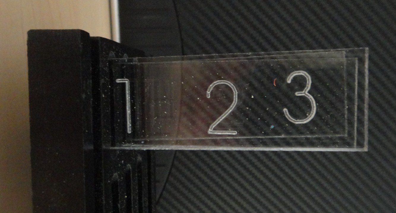
These three pieces make up the back of the inner display case and will be mounted together to form the inner box holding the plex-glass numbered blanks.


These three shots show you why I cut out the first test pieces in styro-foam. This is much less expensive than ruining a good piece of plexi-glass only to find out that something is not right. Notice in the second photo that there is a diagonal cut in the bottom right # 3 pieces. This was a perfect example of why I run a test piece before I commit to a final run of my gcode for the CNC machine. I had an error in a line of code that caused this cut that was not intended to be there in the design. Time well spent and money saved for sure.
I'll be posting more photo and possibly video of this project as I progress further with it.
Video Camera Steadicam
For most people who are not into making their own movies with a video camera the term Steadicam is something they have never heard of but surely have seen in almost every movie that has been made over the past 10 or 15 years. This devise allows anyone to create very steady shots to get professional results with their video. A good example would be a shot of a guy running down the street and the camera in either following him or in from of him. If you try doing this kind of shot without the steadicam your video would be bouncing up and down as you ran with the camera. The steadicam eliminates this up and down motion to give you great looking video.
I am in the process of making such a devise for my video efforts and have most of the components put together at this point in time. A professional Steadicam can cost big bucks and is way out of my league when it comes to that kind of equipment and cost. I was fortunate to come across a video online from another website called The Frugal Filmmaker. I am in the process of building his design with just one little improvement. The design called for a PVC arm to be built but I thought it would look a lot more finished if I made a composite one using fiber glass. I will post photos and the use of this devise once I am farther along with it's construction also. Oh and by the way the steadicam will only cost me around $40 or so. Quite a savings to say the least.
In the meantime here is the video of what it is and how it works from The Frugal Filmmaker website.
Cute little beam bot made out of junk
While I was on letsmakerobots.com, I came across a pretty nice beam bot. It's called the, "Solar Spinner." This robot was constructed out of a container lid, a solar cell (3v by the looks of it), one motor, and a 1381 solar engine. It's kind of like my beam vibrobot, except for the fact that this one spins. If you want to see more on this bot then click this link, http://letsmakerobots.com/node/31569 . Thanks for reading and there will be a new post tomorrow!
Friday, March 2, 2012
Mobile development with haXe NME
Once again real life and work got in the way of nerding about - only this time we managed to combine the two for a while; a few of us are learning mobile development for Android/iOS and the most obvious way forward, as experienced Flash developers, was to go for Flash CS5.5 with it's built-in AIR support.
We've been asked to make a simple app for a tablet (originally an iPad2, but most likely an Android tablet) or a smartphone/hybrid (something like the Samsung Galaxy Note springs to mind) so we've been learning all about tool-chains and cross compiling. Ideally we'd have liked to have stuck with Flash/CS5.5 and AIR, which is ideal for cool kids with the latest smartphones. Creating an app in Flash CS5.5 is a doddle and creating an .apk file is as easy as hitting "publish". Copy the .apk file onto your phone via a usb lead, then use My Files to install the app. If your phone doesn't already have it installed, the app will prompt you to download Adobe AIR (one-time only).

But this is where things started to wrong for us!
We'd only got as far as installing the app when a message popped up to say that our handset wasn't compatible with AIR...

It seems that many smartphones (and tablets) on the market are still running ARM6 processors (such as our Galaxy Ace handsets) and AIR doesn't run on these. We could just ignore these, concentrate on making apps for handsets nearer the top-end of the market and go back to Flash. But there's something about cutting out a large proportion of users, many of whom will be getting Arm6-based handsets (because they are free) on two-year contracts, that doesn't sit right with us. So we've been looking into AIR-free compilers....
It's been a bit of a nightmare!
There have been loads of suggestions, tips and recommendations and we're indebted to the guys at dotBrighton for keeping us going. One thing we're keen on doing is keeping CPU usage to a minimum (with a view to extending battery life while running our apps). Of all the set-ups we've seen, haXe NME looked like it offered what we were looking for - and, it uses an AS3 type syntax with familiar libraries, so the learning curve shouldn't be too steep.

It took over 16 hours to get haXe installed and working properly. There are no easy-start guides on the 'net - we should really have been a bit more organised, written down exactly what we did and how we did it and created one for others to follow. But the truth is, it was so convoluted and we ended up downloading massive 600Mb+ files two and three times (first manually, then allowing the installer to try, then uninstalling and trying again) that we'd only end up with a guide on how not to set up a programming environment!
Something still doesn't ring true that we've used up over 20Gb in disk space just getting this lot working...
But in the end, after installing Java runtimes, Java SDK, Android SDK, Android NPK, Flash Develop, haXe NME, C++, Visual Studio Express, Cygwin and a whole heap of other crap we didn't fully undesrstand, we managed to get and environment working that allowed us to compile the Actuate example from the haXe NME website
Here's our end result. The video shows up to fifty sprites (filled shapes) of differing degrees of transparency with a couple of pngs we added ourselves, to try out the png support.
[video here]
With alpha-support for pngs, and the ability to draw moving objects at different depths, things are quite exciting. A tile-based sprite-blitted game can't be too far away, surely?
Subscribe to:
Comments (Atom)