Tuesday, July 31, 2012
New real life giant mech robot!
Well, it looks like the Japanese have beaten us again in the field of robotics. This time they have created a 13-foot Mech robot that actually moves! The video that unveiled this robot was uploaded on July 30th, so this is a completely new robot. In the video, it shows the robot moving its waist and arms. It also shows a visual on how the robot sees it's environment. At least it sees in multiple colors instead of the creepy red terminator vision. The robot itself can be controlled by a pilot or by a smart phone (Yay, just what we need. Anybody with a smart phone can control a deadly and hostile robot!). The robot has four wheels for mobility, a 30 joint exoskeleton, claws to pick things up, and it can even shoot fireworks! Thanks for reading and check out the video above to see this bot in action!
Monday, July 30, 2012
Electric Car Model Suspension Starting To Take Shape
A very busy day today at the Tinker's Workshop. More design work on my 1/6th scale electric car model with tweaking done to the front suspension and parts being cranked out on the Makerbot 3D printer. Another seven hours onto the design time for a total of 87 hours so far. Lots of tweaking to say the least.

This image is a good view of the front suspension and steering setup for the project. I will need to print out the parts that mount to the upper shocks and the connectors that will hold the rack arm for the rack and pinion steering . The wheels will mount on to the hubs with internal 10-32 bolts threaded into their centers. These will hold the wheels, disk brakes and calipers in place on the model.

Here are the components for one side of the front suspension. Upper and lower suspension arms, wheel mount (disk shaped object) and working shock absorber.

The parts put together makes more sense as to where what parts go where. This is the right front suspension ready to be installed on to the chassis once it is printed.


These two photos are of the steering rack and matching steering shaft gear. The rack is 8 and 1/4 inches long and just fit onto the Makerbot 3D printer. The gear and rack matched up very well and should work great to turn the wheels with the steering wheel. The gear will be mounted onto a 1/4 aluminum shaft directly to the steering wheel. I have to modify the gear so that it can be easily mounted on to the steering shaft with a set screw. The steering wheel will be set up the same way. Also on this shaft will be a spacer mounted on the shaft so that it will not slide out of position once it is installed into the final assembly.
I plan on assembling the model with hardware wherever possible so that it can be disassembled for modifications or repairs if need be. The lucky thing with this model is the sheer size of it which makes assembly easier. Bigger is better and in this case simpler too! I am still playing around with a design for a fiberglass body for the model and am getting closer with that end of it. Just have not found that perfect shape I have been looking for. Like I said more tweaking to do.... a lot more.
How to install the Arduino IDE on Ubuntu 12.04
Its time for another tutorial relating to Arduino! If you have or want to install Ubuntu Linux for working with Arduino then this is the tutorial for you. To install the Arduino IDE, simply go to the software center. Then search "arduino." Don't worry, its free by the way. After you find it, click install. Load up the IDE and your ready to go! Check out my video above to see a video tutorial version.
Friday, July 27, 2012
Electric Car Model Wheels In The Making
The 1/6th scale electric car model project continues today with the making of some rather large wheels that are going together well and are time consuming to print.

This photo is of one of the front wheel rim assemblies that is just stacked up at this point to show you what it all looks like without the tire sections in place. There is a small outer rim then the center five spoked hub and then a larger rear rim. These three pieces took 3 1/2 hours to print on the Makerbot 3D printer.

This photo shows about half of the components that I printed today. The white disks with all of the holes are for the disk brakes that will be in the model. The black disk will be in all three wheel assemblies and are spacers to mount the brake calipers in the wheel assemblies.

This photo shows the before and after sanding detail of the center hubs for the wheels . Once the wheels have been sanded smooth they look very much like a cast plastic part.

After a short discussion with my brother this afternoon I started printing the tires for the wheel assemblies so that each half of the tire were a mirror image of one another. (there are two pieces for each tire) so that the tread would be correct with a "V" form running through it. This was more correct than having both sides of the tire being exactly the same. Just looks a lot better. Thanks Denny!


This gives you a good idea of how large these tires/rim assembly really is. The outer diameter of the tire is 3 3/4 inches. With the parts being this large it is easy to get some real detail in the electric car model. The lower photo shows the rim cavity that will be filled with the disk brake, caliper and center hub. The center hub will mount to a full working suspension and front rack and pinion steering. These parts will also allow for mounting of the front fenders. The assemblies are tight enough when put together that no glue is needed to keep everything in place. The two tire pieces actually hold the entire assembly together.
I finalized the design of the front suspension and the tweaked the rack and pinion also today on the computer model. Hours at this point in just design is around 70 hours so it will be interesting to see how many hours I will have in this model once I have completed it.
I finalized the design of the front suspension and the tweaked the rack and pinion also today on the computer model. Hours at this point in just design is around 70 hours so it will be interesting to see how many hours I will have in this model once I have completed it.
The one nice thing about this model over the Semi and trailer assembly I did some time back is that there are fewer parts and they are larger. It got pretty boring building some of the semi just because there were so many parts that were the same and had to be printed over and over again. (22 wheel assemblies!) Once I get all the wheels printed I will start printing the front suspension and chassis parts. Should be interesting and fun at the same time. I am more than happy with the wheels so far as these assemblies alone are quite impressive with the detail that are in them.
Weaving loom
While away on holiday recently (hence the lack of updates for a while) and with no internet access for a few days (can you believe there are places still where there's no such thing as 24-hour on-demand internet access?!) I found a simple but absorbing time-filler: a child's toy weaving loom

It's really simple to use, consisting of just a wooden frame, a needle and a dolly for raising/lowering alternate weft strings and some wool. Straight out of the box, you simply thread the weft (white) wool up and down the frame, then slide the dolly between the strings and separate them into the little notched grooves.
This causes each string to be raised and lowered alternately. By turning the dolly a quarter-turn backwards and forwards causes the strings to raise and lower. In this example we turn the dolly a quarter turn towards the left....

.... and the string nearest to us moves from the raised to the lowered position. This happens to every other weft string.

By passing the needle, loaded with coloured wool, between the strings then raising/lowering them between each pass, a simple weave pattern quickly starts to form:
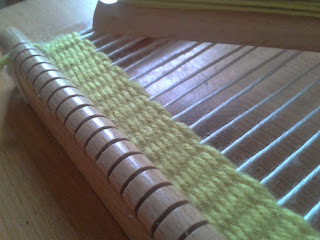
Because the loom came with rather chunky, springy wool, rather than thinner cotton or embroidery silks, the weft strings (white vertical strings) disappear into the final weaved piece as the rows start to build up.
This simple loom is just crying out to be automated, but just exactly how we're not sure.
A stepper motor or servo would be ideal for turning the dolly to raise/lower the strings, and the needle could be passed back and forth using a combination of motorised arms and pulleys but we need to get familiar with the actual act of weaving before trying to build a machine to do the hard work. Adding second (and maybe even third) colours to make an image or pattern would also be pretty cool. Yet another project to add to our ever-increasing list of things started-but-not-yet-finished!
Tuesday, July 24, 2012
New 1/6th Scale Electric Car Model Project Begins!
This past week I have been burning the midnight oil for several days designing a 1/6th scale electric car model. The tally so far for the design has exceeded 50 hours. This vehicle or something like it has been on my mind for years and I am happily now making a model with my Makerbot 3D printer. Printing of the first parts for the model started today and will continue for some time in the future until it is completed. With that in mind here are a few photos of some of the first parts.

I wanted as much detail in the model that I could make and so have decided to have a full suspension complete with working shock absorbers. The puzzle to figure out in the design of the shocks was how to hold it all together. This was accomplished using a small press fit 3/32nd diameter steel pin. The pin is slid into the upper portion of the shock through the slotted inner lower piece. This holds the assembly together without the need for glue. With the 3/4 inch long by 1/2 inch diameter spring and the slot in the lower portion of the shock assembly makes the shocks fully functional. I made the press fit pins by cutting them from a piece of steel rod that I had left over from the Gyrokite project. I used a carbon fiber disk and my Dremel tool to cut the pins to length while they were held firmly in a table vise. (A two second job for each pin.)

The first two of four shocks needed I completed today. They are 2 1/4 inches from mounting center to center (uncompressed) and are 1 and 7/8th inches compressed. I would have completed all four shocks but the hardware store only had a couple of springs that I needed so the other two will have to wait until I can acquire more. All four shocks took three hours to print on the Makerbot.


Here are a couple of good computer images of the electric car model (without a body). It is complete in scale right down to the correct electric motor and lithium battery packs. The model as I said earlier will have a working front and rear suspension and also will have a working rack and pinion steering system. The model will be 24 inches long and 13 inches wide. Overall height will be 7 3/8ths inches. Being this size it will be an impressive model comparable to my Makerbot Semi and trailer and allow me to put nice detail in the building of it. I have a wooden figure of a person that will fit exactly into the model. It (Him? or Her?) stands 12 inches tall and would be six foot tall in real life if and when this model ever becomes a real vehicle some time down the line here at the Tinker's Workshop.
Monday, July 23, 2012
Sunday, July 22, 2012
Nao: evolution of dance
If you remembered YouTube user, TheAmazel, then you already know about his amazing Nao videos. The most popular video he has made was uploaded just a few weeks ago and it already has over 300,000 views. The reason it's popular is because it's a collection of dance moves performed by Nao himself. If you like the original evolution of dance, then I'm sure you'll enjoy this video too!
Improved Wiring
Here is the improved wiring of solar panel setup. One of the picture shows 300 watts output from solar panels being fed into the batteries.


Friday, July 20, 2012
iRobot HQ tour!

Wednesday, July 18, 2012
Review of the sphero robotic ball
Today, I was lucky enough to get a Sphero robotic ball at Brookstone. Once I got home, I ripped open the box and put the bot to the test. Just like in the video ad by Orbotix, this robotic ball really rolls smoothly and it's capabilities with an iPod are truly amazing. I have yet to encounter a problem with this little robot. My favorite features are that I can change it's color and the robot charges using wireless induction technology. Thanks for reading and check out the video above to see my review and use of the Sphero robotic ball.
Tuesday, July 17, 2012
CNN video: Robots vs. terrorists
A new robotics video was uploaded today by the official CNN YouTube channel. The video features a SWAT team using a small robot scout to help them capture a criminal. They talk about how the little robot can help them during certain operations. The robot itself has two all terrain wheels, a camera, microphone, and even IR sensors. All these high tech features help law enforcement officers capture the criminals and save the day. Thanks for reading and check out the video above to see the bot in action!
Monday, July 16, 2012
Gyrokite Project Completed
This past month or so I have been working on the Gyrokite project. Today I put the finishing touches on it and am happy as usual that it turned out as well as it has with all the tinkering that needed to be done to design and build it. First off for those of you that have not been following my blog for that amount of time this gyrocopter is a remake of an old design from the 1960's I came across and decided to update and build. It is a kite so the name Gyrokite was born. (My idea). The finished gyro stands 19 3/4 inches tall and has a 19 inch long fuselage. The dual counter rotating main rotors are 36 inches from tip to tip and the tail structure is 9 1/2 inches across.


The fuselage is constructed of fiberglass and it has at least fourteen coats of primer on it. This was primed and wet sanded, primed and wet sanded over an over again before five coats of banner red paint was applied. As you can see from the photos it was worth the effort to get this kind of finish on the Gyrokite.


Doing the final assembly of the Gyrokite turned out to be a comedy of errors. I had assembled the main rotors and top vane on to the main rotor shaft assembly only to find out that the top rotor hub was assembled upside down. This caused the top main rotor to tilt down instead of up and collide with the bottom rotor. Not a good idea at all. Also the top wind vain was completely backward in the assembly. I had to remove the main steel 3/32nd rotor shaft and had to make a new one to replace it to correct the problems. This only took about ten minutes or so but at least everything was made right very quickly and it is now ready to fly.
For more information about the construction of this little beauty go back to the blog here over the past month as I have posted all information about how the Gyrokite was put together from the main rotors to the landing skids. I will have to get a good windy day to test fly my latest project and hopefully I can get a hand with shooting some video of the maiden flight. If I can I will post the video here when I do. My brother who was visiting me over the weekend hopes that it will fly as good as it looks. I wish for the same but even if it does not turn out like I hope and believe it will this project will in no way be a failure in my eyes if it does not fly well or if at all. (But I am still keeping my fingers crossed for the first flight!) I learned a lot about finishing fiberglass so that I can get a near perfect surface for painting because of this project. That alone was worth the effort and something that I will carry forward in future fiber glassing projects. Your never to old to learn new things, especially here at the Tinker's Workshop.
Sunday, July 15, 2012
New hexapillar hexbug is merged with a target gift card

Thursday, July 12, 2012
End of Episode-1
Truly speaking there is nothing in the world like a joy of accomplishment...The adventure i started almost a year ago ended up quite nicely... The target achieved was well-worth of experience with a steep learning curve... This endeavor encompasses many failures but i think their is no gain without learning from failures...
Yesterday i installed the solar system at my Karachi home and got the results as desired. Today when i sleep getting cool breeze of Air-conditioner i can feel a bit of relief while thinking of my family at Karachi.
In near future i shall install six more panels on the same structure. This structure can withstand easily 12 solar panels total wattage up-to 1200Watts..


 The racks are under fabrication for holding the batteries and UPS stuff...

Yesterday i installed the solar system at my Karachi home and got the results as desired. Today when i sleep getting cool breeze of Air-conditioner i can feel a bit of relief while thinking of my family at Karachi.
In near future i shall install six more panels on the same structure. This structure can withstand easily 12 solar panels total wattage up-to 1200Watts..


How a shift register works
This was a quick-and-dirty project just to understand how our shift registers from Farnell work. The block diagram on the datasheet makes things pretty simple, but we still need to make sure we're toggling the right lines to "flush" the data into the device:

From this block diagram, we can see that any data clocked into the shift register is held in a buffer, and only transferred onto the output pins when the RCK line is toggled (in this case, according to the "truth table" from low to high)

So we built a quick usb device (for getting data quickly from our PC to the end device) using a PIC 18F255 microcontroller and used it to clock data in/out of the shift register. The PIC was connected to our SMT LED breakout board as follows:
PORTB.5 -> serial clock in (SCLK)
PORTB.4 -> register clock (RCLK)
PORTB.3 -> serial data in (SI)

The layout/PDF for the breakout board is here:
SOIC-to-DIP breakout With Leds (for shift register)
(don't forget that this is for SMT components, not through-hole, so the final etched board will be mirrored. That's why PIN1 is marked on the top right, not top left, and Vcc- pin16 - is top left. You'll need to use your imagination to "flip" this and get the pins in the right place!)
A shift register is quite easy to work with, but until you actually get your hands on one and make it work, it can be difficult to fully appreciate what's needed. A shift register can be used in a variety of ways, you can tie the clock lines together (to save pins) but that only adds to the complexity. You can daisy-chain the registers, by enabling the output line and have one SR feed the next in a chain and so on.
We're going to concentrate on simply getting serial data into the device, and displaying it on a sequence of LEDs. This project will form the basis for future projects by reducing the pin-count needed to individually control lots of separate LEDs. Having learned from the word clock in November, we're sticking to surface mount LEDs this time - no way are we going to be spending hours and hours drilling hundreds of holes again!

With the shift register hooked up to the PIC microcontroller, we dropped some simple code onto the PIC and wrote a quick VB app to send data to the PIC. The PIC simply takes a single byte value and sends it to the shift register in the following sequence:
Here's the Oshonsoft Basic code for our PIC:
The idea is that we'll send a byte value to our PIC controller board (via usb) which it will then clock into the shift register. It's important to note that we've only used six of the possible eight output pins on the shift register. So the first and last bits (mapped to pins 7 and 15 on the shift register) aren't actually connected to an LED. Any data value sent will be displayed as X 1 1 1 1 1 1 X
To see this in action, we can send the byte value 47 to the PIC.
In binary, this is represented by 0 0 1 0 1 1 1 1
Since our board is ignoring the first and last bits (why didn't we just connect them up to make explaining this a bit easier?!) this gives the LED lighting sequence X 0 1 0 1 1 1 X
Instead of just typing random numbers, converting to binary and comparing the results, we built a simple VB app to generate a byte value and send it to the PIC microcontroller:
We set the value of the serial input line to match the value of the first "bit" in our byte value (either on/high or off/low) then toggle the serial clock line. This pushes the first bit into the shift register. When then set the serial line to match the second bit (either on/high or off/low) and toggle the serial clock line again. This pushes the first bit along Ishifts it) and pushes the second bit into the register.
After doing this eight times, our shift register contains the byte value we sent over a single serial data line. To get the value to display by lighting our LEDs, we need a low-to-high transistion on the RCLK pin. Until this pin goes high, the data sent to the shift register sits in the "top part" and doesn't actually affect the output pins. When the RCLK pin goes high, the value in the shift part of the register is "flushed" into the latching register which controls the output pins QA-QH (and the sequence of LEDs changes)
Btw - it turns out that we did indeed mount the shift registers the correct way around on our little breakout board, despite not finding a pin1 marker on the casing. If anyone else is using these 74HC595 SOIC shift registers, they should be mounted, rotated 90 degrees to the right and pin1 is the top-left-most pin as per the datasheet!


From this block diagram, we can see that any data clocked into the shift register is held in a buffer, and only transferred onto the output pins when the RCK line is toggled (in this case, according to the "truth table" from low to high)

So we built a quick usb device (for getting data quickly from our PC to the end device) using a PIC 18F255 microcontroller and used it to clock data in/out of the shift register. The PIC was connected to our SMT LED breakout board as follows:
PORTB.5 -> serial clock in (SCLK)
PORTB.4 -> register clock (RCLK)
PORTB.3 -> serial data in (SI)

The layout/PDF for the breakout board is here:
SOIC-to-DIP breakout With Leds (for shift register)
(don't forget that this is for SMT components, not through-hole, so the final etched board will be mirrored. That's why PIN1 is marked on the top right, not top left, and Vcc- pin16 - is top left. You'll need to use your imagination to "flip" this and get the pins in the right place!)
A shift register is quite easy to work with, but until you actually get your hands on one and make it work, it can be difficult to fully appreciate what's needed. A shift register can be used in a variety of ways, you can tie the clock lines together (to save pins) but that only adds to the complexity. You can daisy-chain the registers, by enabling the output line and have one SR feed the next in a chain and so on.
We're going to concentrate on simply getting serial data into the device, and displaying it on a sequence of LEDs. This project will form the basis for future projects by reducing the pin-count needed to individually control lots of separate LEDs. Having learned from the word clock in November, we're sticking to surface mount LEDs this time - no way are we going to be spending hours and hours drilling hundreds of holes again!

(this board was made up with solder paste and a cheap nasty "fire-starter" soldering iron from Farnell. Hence the scorched traces and missing pin header where the connect-to-ground jumper burned away and had to be fixed with a bit of spare wire!)
With the shift register hooked up to the PIC microcontroller, we dropped some simple code onto the PIC and wrote a quick VB app to send data to the PIC. The PIC simply takes a single byte value and sends it to the shift register in the following sequence:
Here's the Oshonsoft Basic code for our PIC:
Define CLOCK_FREQUENCY = 20
Define CONFIG1L = 0x24
Define CONFIG1H = 0x0c
Define CONFIG2L = 0x38
Define CONFIG2H = 0x00
Define CONFIG3L = 0x00
Define CONFIG3H = 0x03
Define CONFIG4L = 0x80
Define CONFIG4H = 0x00
Define CONFIG5L = 0x0f
Define CONFIG5H = 0xc0
Define CONFIG6L = 0x0f
Define CONFIG6H = 0xe0
Define CONFIG7L = 0x0f
Define CONFIG7H = 0x40
UsbSetVendorId 0x1234
UsbSetProductId 0x1234
UsbSetVersionNumber 0x1122
UsbSetManufacturerString "Nerd Club"
UsbSetProductString "Generic USB HID Device"
UsbSetSerialNumberString "1111111111"
UsbOnIoInGosub input_report_before_sending
UsbOnIoOutGosub output_report_received
UsbOnFtInGosub feature_report_before_sending
UsbOnFtOutGosub feature_report_received
AllDigital
Dim i As Byte
Dim pattern As Byte
Symbol rclk = PORTB.4
Symbol sclk = PORTB.5
Symbol si = PORTB.3
UsbStart
i = 0
pattern = 255
loop:
UsbService
If i = 0 Then
Gosub senddata
i = 1
Endif
Goto loop
End
senddata:
'prepare the shift register "flush" pin
Low rclk
'send data to the shift register
If pattern.0 = 1 Then High si Else Low si
Gosub toggleserialclock
If pattern.1 = 1 Then High si Else Low si
Gosub toggleserialclock
If pattern.2 = 1 Then High si Else Low si
Gosub toggleserialclock
If pattern.3 = 1 Then High si Else Low si
Gosub toggleserialclock
If pattern.4 = 1 Then High si Else Low si
Gosub toggleserialclock
If pattern.5 = 1 Then High si Else Low si
Gosub toggleserialclock
If pattern.6 = 1 Then High si Else Low si
Gosub toggleserialclock
If pattern.7 = 1 Then High si Else Low si
Gosub toggleserialclock
'flush the shift data onto the output pins
High rclk
Return
toggleserialclock:
Low sclk
WaitUs 50
High sclk
Return
feature_report_received:
Return
feature_report_before_sending:
Return
output_report_received:
pattern = UsbIoBuffer(0)
Gosub senddata
Return
input_report_before_sending:
Return
The idea is that we'll send a byte value to our PIC controller board (via usb) which it will then clock into the shift register. It's important to note that we've only used six of the possible eight output pins on the shift register. So the first and last bits (mapped to pins 7 and 15 on the shift register) aren't actually connected to an LED. Any data value sent will be displayed as X 1 1 1 1 1 1 X
To see this in action, we can send the byte value 47 to the PIC.
In binary, this is represented by 0 0 1 0 1 1 1 1
Since our board is ignoring the first and last bits (why didn't we just connect them up to make explaining this a bit easier?!) this gives the LED lighting sequence X 0 1 0 1 1 1 X
Instead of just typing random numbers, converting to binary and comparing the results, we built a simple VB app to generate a byte value and send it to the PIC microcontroller:
Although focus isn't brilliant you should be able to see that by clicking the onscreen LEDs, the VB app is generating a byte value (from a binary representation of the LED states). This value is sent to the PIC, which turns the byte value back into a series of bits, which are then transmitted to the shift register, one bit at a time.
We set the value of the serial input line to match the value of the first "bit" in our byte value (either on/high or off/low) then toggle the serial clock line. This pushes the first bit into the shift register. When then set the serial line to match the second bit (either on/high or off/low) and toggle the serial clock line again. This pushes the first bit along Ishifts it) and pushes the second bit into the register.
After doing this eight times, our shift register contains the byte value we sent over a single serial data line. To get the value to display by lighting our LEDs, we need a low-to-high transistion on the RCLK pin. Until this pin goes high, the data sent to the shift register sits in the "top part" and doesn't actually affect the output pins. When the RCLK pin goes high, the value in the shift part of the register is "flushed" into the latching register which controls the output pins QA-QH (and the sequence of LEDs changes)
Btw - it turns out that we did indeed mount the shift registers the correct way around on our little breakout board, despite not finding a pin1 marker on the casing. If anyone else is using these 74HC595 SOIC shift registers, they should be mounted, rotated 90 degrees to the right and pin1 is the top-left-most pin as per the datasheet!

Wednesday, July 11, 2012
Gyrokite Fuselage Almost Ready For Final Paint
I've been busy today making adjustments and modifications to my Gyrokite project. One of the main changes that needed to be made was the replacement of the landing skids. The original design for the skids was to short in length to support the fuselage correctly. The tail of the fuselage ended up sitting on the ground when placed on a flat surface.

This photo shows the Gyrokite with the new skids installed. They are two inches longer than the original design and have additional bracing for strength. They actually look better and will give the Gyrokite a better footing when sitting on the ground. This is where the new Makerbot 3D printer was a big plus as the skids now are eight inches long. On an earlier Makerbot printer I was using in Davenport you could not make parts any bigger than three inches in length on a good day.

I also got the tail section of the Gyrokite mounted onto the rear of the fuselage today. All the primer has been wet sanded smooth and is now ready for final painting of the fuselage. This will happen in the next couple of days along with the final assembly of the main rotors, vertical wind vane, and mounting hardware to the internal mast support. Once I complete this portion of the work for this project I will post the final photos and be ready to test fly it once we get a good windy day. Just will have to keep my fingers crossed that it flies as well as it already looks!
Robotics kits from erobotkits.com

SOIC/SOP to DIP breakout board
We recently bought some shift registers from Farnell but being SMT they're not easy to use on a breadboard /prototyping system so we knocked up a simple breakout board for them. These boards should suffice for any SOIC device, to make it suitable for plugging into a breadboard.
Interestingly, the parts are listed as SOP-sized but in ExpressPCB there were no component layouts for SOP. We chose SOIC instead and the layout was a perfect match. So is SOP and SOIC the same layout? The jury's still out on that one.
In the meantime, here's our breakout board layout.
Don't forget to download and print from Adobe Acrobat Reader, not directly from Google Chrome!
Soic Breakout 16 Pin
Tuesday, July 10, 2012
Just one of those nights
Tonight was just one of those nights where nothing seemed to go right.
First off, our "quick-and-dirty" PCB took far longer than we'd hoped, given that it didn't print properly in the first place.
Then we tried adding a dial of numbers to our petanque score keeping device. NewlyDraw lets you print and "scan" (engrave) from a single file, so we added an engrave layer to our cutouts and set the laser going.
The etching looked lovely as the head whizzed backwards and forwards, but when it came to cutting, things didn't look quite right:

For whatever reason, the etching and the cutting just didn't line up (yet looked perfect onscreen!)
Undeterred, we decided to try out some paint-filling ideas to make the numbers really stand out. A few CNC forums suggest simply using acrylic paint to fill the engraving, and wipe off with a damp cloth. It didn't really work for us!

We tried wiping the etching both while the paint was still wet, and after it had dried. The results were noticably different, with wiping once dried giving a better result (but still not brilliant)
 (Numbers 5 and 6 were filled, left to dry, then wiped clean. Then other numbers were wiped while the paint was still wet on the surface)
So neither the etching, cutting nor painting was much of a success.
Our earlier PCB making was only partially successful, but, determined to salvage something from tonight, we soldiered on to make a test board.
We bought some shift registers from Farnell last night (ordered 7pm last night, arrived 2pm this afternoon - amazing service!) for another large LED-based project. The breakout board was supposed to be a quick-and-dirty way of testing out how they worked. So we added some surface mount LEDs to pins 1-6 and mounted a 74HC595 register on the board.
The only trouble was, we can't find the "pin one" marker on the casing. Normally IC chips have a dot in one top left corner, to indicate which pin is pin one. But this time, we couldn't see one!
So we've just mounted one and hoped for the best.
Now we need to get it hooked up to a microcontroller and see if we can get those LEDs to light up. If they do, we know we've got it right. The problem comes if they don't.
Is it due to a dodgy connection, some badly written PIC code, mis-understanding how the shift register works, or has the IC been mounted the wrong way around?
There's only one way to find out - but it's almost midnight now and there's little time left to go digging about looking for that PIC programmer.....
First off, our "quick-and-dirty" PCB took far longer than we'd hoped, given that it didn't print properly in the first place.
Then we tried adding a dial of numbers to our petanque score keeping device. NewlyDraw lets you print and "scan" (engrave) from a single file, so we added an engrave layer to our cutouts and set the laser going.
The etching looked lovely as the head whizzed backwards and forwards, but when it came to cutting, things didn't look quite right:

For whatever reason, the etching and the cutting just didn't line up (yet looked perfect onscreen!)
Undeterred, we decided to try out some paint-filling ideas to make the numbers really stand out. A few CNC forums suggest simply using acrylic paint to fill the engraving, and wipe off with a damp cloth. It didn't really work for us!

We tried wiping the etching both while the paint was still wet, and after it had dried. The results were noticably different, with wiping once dried giving a better result (but still not brilliant)

So neither the etching, cutting nor painting was much of a success.
Our earlier PCB making was only partially successful, but, determined to salvage something from tonight, we soldiered on to make a test board.
We bought some shift registers from Farnell last night (ordered 7pm last night, arrived 2pm this afternoon - amazing service!) for another large LED-based project. The breakout board was supposed to be a quick-and-dirty way of testing out how they worked. So we added some surface mount LEDs to pins 1-6 and mounted a 74HC595 register on the board.
The only trouble was, we can't find the "pin one" marker on the casing. Normally IC chips have a dot in one top left corner, to indicate which pin is pin one. But this time, we couldn't see one!
So we've just mounted one and hoped for the best.
Now we need to get it hooked up to a microcontroller and see if we can get those LEDs to light up. If they do, we know we've got it right. The problem comes if they don't.
Is it due to a dodgy connection, some badly written PIC code, mis-understanding how the shift register works, or has the IC been mounted the wrong way around?
There's only one way to find out - but it's almost midnight now and there's little time left to go digging about looking for that PIC programmer.....
Don't print PDFs from Google Chrome!
It's frustrating but for the second time, we've ended up with some etched circuit boards that are too small. The first time was back in November last year, when making our LED charlie-plexed matrix and we couldn't work out back then what had gone wrong.
Here's a quick rundown of how we etch our boards:
Firstly, draw the schematic in ExpressPCB then transfer the design onto their PCB layout software.
Then print the PCB layout but instead of sending it to a printer, direct it to CutePDF virtual printer. This creates a full-scale PDF file which can be uploaded, emailed and generally shared around the place.
That's how we create all our circuit boards, generating PDFs then emailing them to our machine that's connected to a big Xerox Phaser for printing onto press-n-peel.
Tonight we wanted to knock up a quick SOIC-to-DIP breakout board. Then as an after-thought, we added some LEDs to one side of the board. As always, create PDF then email to the printer machine.

But this time, the circuit board came out about 90%-95% of full size. Notice how the pins "fan out" as they aren't properly lined up with the PCB. The holes on the board are closer together than the 0.1" pitch of the pin headers. Yet in the PDF file, the holes are exactly 0.1" apart.

Now the only difference we can see between our "normal" method of creating PCBs and what we did tonight is that instead of downloading the file to our library, opening with Adobe PDF reader and printing from there, we just clicked the link in the web-mail and the PDF opened in Google Chrome.
Which leads us to the conclusion that the PDF viewer in Google Chrome (or at least the printer support in it) is a bit flaky. In fact, we've never been impressed by Google Chrome's print preview (it used to get confused when the printer default layout was landscape) but in recent months it's got better. Or, perhaps after tonight, we can only conclude that it hasn't!
In short, always download your PDF layouts and print from Adobe's Acrobat Reader to make sure your circuit boards are printed at 100% scale.
New robot caterpillar made from bamboo

Monday, July 9, 2012
Makerbot Replicator Extruder Centering Solution
The past couple of weeks I have been enjoying my new Makerbot Replicator 3D printer but have noticed something that was not to my liking. When I loaded a file to be printed on the Makerbot I would center the part and save it but it would not print in the center of the machine even though the software showed the part was in the center of the build platform. This is really not a problem on this 3D printer as long as you do not try to make very big parts. Other users online have tried and the parts will fail simply because they are not centered and will run off the edge of the build platform. I did not want this to happen so with this post I will show you how I solved this problem quickly and simply without a hassle.

The image above is the ReplicatorG software screen that I use to set up files to be printed on the Makerbot Replicator 3D printer. This software is the standard used to making 3D parts on any home use 3D printer. The display screen helps me rotate, mirror, scale and view the computer designed part that I wish to make. In this view is a very small part that is used in the Gyrokite project that I am currently working on. I used this small part for testing to get the calibration figured out on the Makerbot.
I did some research online to see if I could find a solution to my problem of parts not printing at the center location even though it shows that it should in the software setup. Turns out that a lot of other guys are having the same problem. The only true piece of advise that was any help was a procedure I found to do a calibration set up for centering the printer. I thought "Great, This will be perfect!" I ran the software but could not get it to make the corrections I needed on the machine.
The procedure for making the correction needed is to click "File", then "Scripts", "Calibration" and lastly click "The Replicator Calibration.Gcode" selection. This will set up a Gcode file in the ReplicatorG software screen. Press the run button and you will get a menu that says "Move the extruder carriage until it lies in the dead center of the build plate. Then press "Yes" to continue. I moved the extruder carriage to dead center and the platform exactly the thickness of a sheet of paper from the print nozzles. Then I pressed "Yes" to finish the procedure. After finishing this procedure I thought "Now my prints will be centered perfectly" No so. I ran another test part and it had not done anything. I measured the position of the print and found that it was printed 3/4 of an inch to the right of center. Then a brainstorm hit me. Why not just adjust the centering of the machine to 3/4 of an inch to the left. Worth a shot I thought. So before I ran the procedure again I aligned the print heads to the center to start and then readjusted them to be 3/4 of an inch off to the left. Then I ran the procedure again.


These two photos show the before and after start of the simple part that I was testing. The single circle is what was printed before making any changes to the printer extruder heads center location which is the incorrect location for the part. The double circle is the correct location (dead center) after adjusting the start location by 3/4 of an inch to the left.
Since making this adjustment I have ran at least a half dozen more parts and all are centered perfectly on the build platform. Why the procedure for making the correction in the first place failed I have no idea. But with that failure I found a simple solution that works. Can't find any fault with that for sure. So hopefully a lot of other people who own the Makerbot Replicator will read what I have posted here and get their machine centered and printing just the way they want also. Let the large 3D printing begin!
Subscribe to:
Posts (Atom)